Op-Amp Simulator
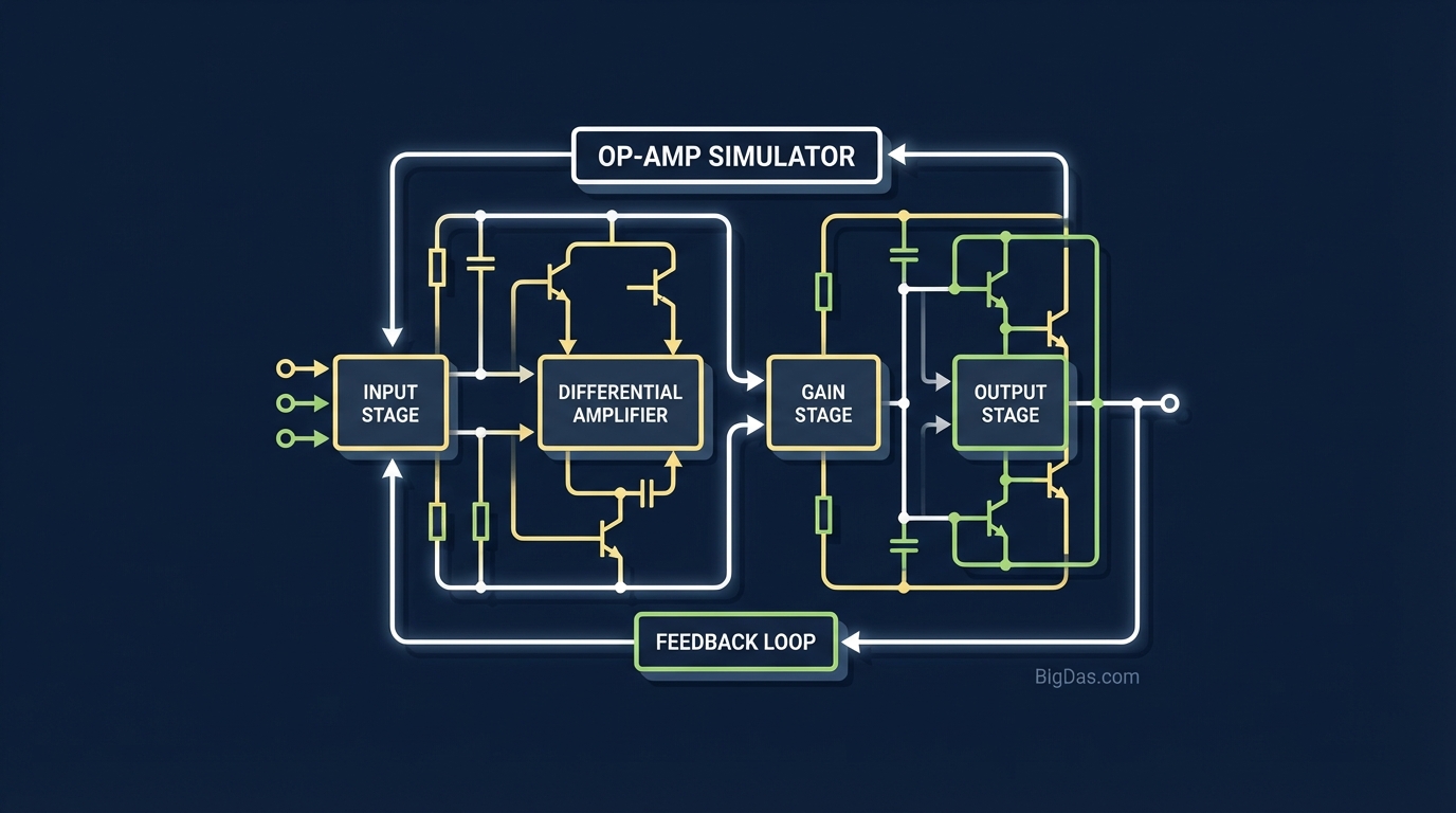 Modern scientific illustration of Op-Amp Simulator
Master Circuit Design: The Ultimate Online Op-Amp Simulator for Real-Time Analysis
Electronics design is an art form rooted in physics, but the gap between a schematic on paper and a functioning circuit on a breadboard can be frustratingly wide.
For electrical engineering students, hobbyists, and professional circuit designers, the Operational Amplifier (Op-Amp) is the fundamental building block of analog electronics. Whether you are conditioning a sensor signal, building an audio pre-amplifier, or designing a complex control system, the behavior of your Op-Amp dictates the success of your project.
But calculating feedback resistors, determining gain, and predicting phase shifts manually is tedious and prone to error. Worse, static calculations don't show you how the signal behaves dynamically over time.
Enter the Op-Amp Simulator.
This isn't just a calculator; it is a best-in-class simulation environment designed to visualize the behavior of Inverting, Non-Inverting, and Buffer configurations in real-time. In this guide, we will explore how this tool works, why it is essential for modern electronics workflows, and how you can use it to perfect your circuit designs before you ever touch a soldering iron.
What is the Op-Amp Simulator?
The Op-Amp Simulator is a specialized, browser-based engineering tool that models the electrical behavior of standard operational amplifier circuits. Unlike generic electronics calculators that only provide a static output voltage value, this tool functions as a virtual oscilloscope and circuit lab combined.
It focuses on the three most critical topologies used in 90% of analog signal chain designs:
- Inverting Amplifier: Where the output is out of phase with the input.
- Non-Inverting Amplifier: Where the output matches the input phase with added gain.
- Voltage Follower (Buffer): Used for impedance matching with unity gain.
By inputting your component values (Resistors, Input Voltages, and Supply Rails), the simulator computes the transfer function and generates a real-time waveform visualization. This allows you to see exactly how your input signal is amplified—or distorted—instantaneously.
Key Features & Benefits
Why is this specific Op-Amp Simulator considered the gold standard for quick circuit analysis? Here is what sets it apart:
1. Real-Time Waveform Visualization
Numbers on a screen are abstract. Seeing a sine wave clipped because your gain is too high is intuitive. The tool plots $V_{in}$ (Input) vs. $V_{out}$ (Output) on a time domain graph, allowing you to visually inspect phase shifts and signal integrity.
2. Dynamic Component Adjustment
Change your feedback resistor ($R_f$) value and watch the waveform grow or shrink instantly. This feature is crucial for understanding the relationship between component ratios and amplifier gain ($A_v$).
3. Saturation Detection (Rail-to-Rail Limits)
In the real world, an Op-Amp cannot output more voltage than its power supply provides. Many simulators ignore this. Our Op-Amp Simulator accounts for supply rails, visually demonstrating "clipping" if your calculated output voltage exceeds the physical limits of the device.
4. Comprehensive Configuration Support
Switch seamlessly between Inverting, Non-Inverting, and Buffer modes without refreshing the page or losing your data. This allows for rapid A/B testing of different circuit topologies.
5. High-Precision Math Engine
Behind the user-friendly interface lies a robust computation engine that handles floating-point arithmetic with high precision, ensuring that your gain calculations are accurate enough for professional engineering specifications.
Deep Dive: Supported Circuit Configurations
To get the most out of the Op-Amp Simulator, it helps to understand the physics it is modeling. Here is what the tool simulates for each configuration.
The Inverting Amplifier
This is the most common configuration for audio mixing and signal scaling. The input signal is applied to the inverting input (-) through a resistor ($R_{in}$), while the non-inverting input (+) is grounded.
- The Simulator Calculation: $V_{out} = -V_{in} \times (R_f / R_{in})$
- What to Look For: In the simulator's waveform graph, pay attention to the Phase Shift. You will see that when the input wave goes up (positive), the output wave goes down (negative). This is a 180-degree phase shift, a characteristic trait visualized perfectly by the tool.
The Non-Inverting Amplifier
Used when you need high input impedance and voltage gain without flipping the signal phase. The input signal goes directly to the non-inverting input (+).
- The Simulator Calculation: $V_{out} = V_{in} \times (1 + R_f / R_{in})$
- What to Look For: Notice that the output waveform is perfectly aligned with the input waveform in the time domain. This confirms zero phase shift.
The Voltage Buffer (Unity Gain Follower)
This circuit has a gain of 1. It doesn't amplify voltage; it amplifies current capability and isolates stages.
- The Simulator Calculation: $V_{out} = V_{in}$
- What to Look For: The simulator will show the Input and Output lines perfectly overlapping. While visually simple, this confirms that your signal is passing through unchanged in amplitude, which is critical for impedance matching verification.
Step-by-Step Guide: How to Use the Op-Amp Simulator
Ready to design? Follow this workflow to utilize the tool effectively.
Step 1: Select Your Topology
Choose your desired circuit configuration from the dropdown menu: Inverting, Non-Inverting, or Buffer. The schematic diagram on the screen will update to reflect your choice.
Step 2: Set Power Rails
Define your positive ($+V_{cc}$) and negative ($-V_{ee}$) supply voltages.
- Tip: Standard values are often +12V/-12V or +5V/0V (single supply). Setting this correctly is vital to seeing realistic saturation/clipping effects.
Step 3: Input Component Values
Enter the values for:
- Input Voltage ($V_{in}$): The amplitude of the signal you want to amplify.
- Input Resistor ($R_{in}$): The resistor connecting the source to the Op-Amp.
- Feedback Resistor ($R_f$): The resistor connecting the output back to the input.
Step 4: Analyze the Data
The tool will instantly calculate:
- Gain ($A_v$): The factor by which the signal is multiplied.
- Output Voltage ($V_{out}$): The theoretical peak voltage.
Step 5: Visualize the Waveform
Look at the graph.
- Green Line: Your Input Signal.
- Red Line: Your Output Signal.
- Flat Tops: If the Red Line looks like a square wave with flat tops, your gain is too high, and the Op-Amp is clipping (hitting the power rails). Reduce $R_f$ or increase the power supply voltages to fix this.
Why You Need This Tool (Use Cases)
Who benefits from an online Op-Amp Simulator?
1. Electronics Students
Textbooks are full of formulas like $V_{out} = -V_{in}(R_f/R_{in})$. However, memorizing the formula isn't the same as understanding the concept. This tool bridges the gap between theory and application, helping students visualize phase inversion and gain limits for lab reports and homework.
2. Audio Equipment Designers
Building a guitar pedal or a microphone pre-amp? You need to know exactly how much gain your stage provides and if it will distort the signal. Use this simulator to tune your resistor values to get the perfect "clean" signal before you start breadboarding.
3. Sensor Integration Engineers
Sensors (like temperature or pressure sensors) often output very small voltages (millivolts). These signals must be amplified to be read by an Arduino or Microcontroller (0-5V). This simulator helps you calculate the exact resistors needed to scale a 0.1V sensor signal up to a readable 3.3V or 5V range.
4. Hobbyists and Makers
If you are debugging a circuit and your output looks wrong, use this simulator as a "sanity check." If the simulator says you should have 5V out, but your multimeter reads 1V, you know you have a loose connection or a damaged component.
Pro-Tips: Getting the Most Out of Your Simulation
To truly master this tool, keep these advanced considerations in mind:
- Watch the Rails: The most common mistake in Op-Amp design is demanding more voltage than the supply can give. If your calculation requires 15V output, but your supply is only 12V, the simulator will show you the clipped waveform. Always design with 1V-2V of headroom.
- Understanding Impedance: While this simulator handles voltage perfectly, remember that in the real world, $R_{in}$ sets the input impedance of an Inverting Amplifier. Don't set $R_{in}$ too low (e.g., 10 ohms), or you will load down your source. Stick to values between 1k$\Omega$ and 100k$\Omega$ for general use.
- Frequency Response: This tool simulates idealized Op-Amps at standard frequencies. Remember that real Op-Amps have a "Gain Bandwidth Product" (GBP). At extremely high frequencies (MHz range), the gain will drop off—a concept known as Bode Plot analysis.
Frequently Asked Questions (FAQ)
Q: Why is my output waveform flat at the top and bottom?
A: This is called Clipping or Saturation. It means the calculated output voltage exceeds the power supply voltage you entered. To fix this, decrease the Gain (lower $R_f$) or increase the Power Supply Voltage.
Q: Can I simulate a Single Supply circuit (e.g., 0V to 5V)?
A: Yes. Set the Negative Supply ($-V_{ee}$) to 0V and the Positive Supply ($+V_{cc}$) to 5V. Note that for AC signals, you may need a virtual ground reference for the standard Inverting/Non-Inverting topologies to work correctly without clipping the negative half of the cycle.
Q: What is the difference between the Inverting and Non-Inverting configuration?
A: The Inverting amplifier flips the signal upside down (180° phase shift) and can reduce gain below 1. The Non-Inverting amplifier keeps the signal phase the same and always has a gain of 1 or greater.
Q: Does this simulator account for Op-Amp Slew Rate?
A: This simulator focuses on ideal steady-state analysis and gain logic. For extreme high-frequency transient analysis involving slew rate limitations, a full SPICE simulation suite might be required, but for 95% of general analog design, this ideal model is sufficient and much faster to use.
Conclusion
The Op-Amp Simulator is more than just a convenience; it is a vital visualization instrument for anyone working with analog electronics. By providing immediate feedback on gain, phase, and saturation, it eliminates the guesswork involved in circuit design.
Whether you are a student struggling to understand the difference between inverting and non-inverting inputs, or a seasoned engineer performing a quick gain calculation for a new PCB design, this tool provides the precision and visual clarity you need.
Stop guessing resistor values. Start visualizing your circuits today.
[Launch Op-Amp Simulator Now] (Insert Tool Link Here)