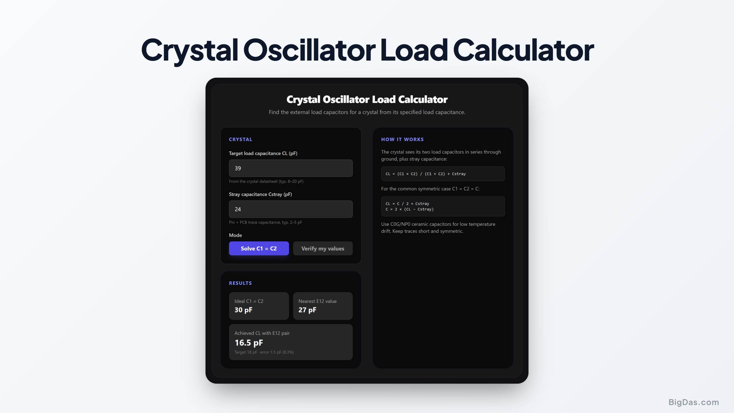
Crystal Load Capacitor Calculator
 Generated infographic and interface snapshot for Crystal Oscillator Load Calculator
Pick the right load capacitors so your crystal oscillates on frequency.
Free Crystal Load Capacitor Calculator Online — Big Das
The Big Das Crystal Oscillator Load Calculator converts a crystal's specified load capacitance into the two external capacitor values your Pierce oscillator needs, rounded to the nearest E12 stock value with achieved-CL readback.
What Is Load Capacitance?
Every parallel-mode crystal is calibrated at a specified *load capacitance
- CL, typically 8–20 pF. The oscillator circuit must present exactly that capacitance or the crystal runs off frequency. The oscillator sees its two load capacitors C1 and C2 in series through ground, plus the unavoidable stray capacitance of pins and PCB traces (typically 2–5 pF).
How to Use the Calculator
- Enter the crystal's target CL from its datasheet.
- Enter your estimated stray capacitance — 3 pF is a good starting point for a compact layout.
- In Solve mode, read the ideal C1 = C2 value, the nearest E12 value, and the CL that pair actually achieves.
- Switch to Verify mode to check what load an existing capacitor pair presents.
Formulas Used
General (asymmetric):
CL = (C1 · C2) / (C1 + C2) + Cstray

Symmetric (C1 = C2 = C):
CL = C/2 + Cstray
C  = 2 · (CL − Cstray)
The solved value is then rounded to the nearest E12 series value (1.0, 1.2, 1.5, 1.8, 2.2, 2.7, 3.3, 3.9, 4.7, 5.6, 6.8, 8.2 and their decades).
Worked Example
A 16 MHz microcontroller crystal specifies CL = 18 pF.
Estimate stray capacitance as 3 pF.
C = 2 × (18 − 3) = 30 pF ideal.
Nearest E12 value: 33 pF.
Achieved CL = 33/2 + 3 = 19.5 pF — about 8% high, fine for most clock applications. A trimmer or a mix of 27 pF and 33 pF gets closer if you need it.
Common Use Cases
Microcontroller crystal circuits (STM32, AVR, PIC, ESP32)
Real-time clock crystals at 32.768 kHz
Watchdog and timing oscillators
Diagnosing crystals that drift or fail to start
Selecting parts before sending a board to fabrication
Frequently Asked Questions
What happens if the load capacitance is wrong?
The crystal oscillates off its marked frequency — roughly tens of ppm per pF of error. Too little capacitance also reduces loop gain margin and can prevent startup.
What value should I use for stray capacitance?
2–5 pF covers most layouts. Tight, short traces near the MCU pins sit near the low end; long traces, vias and sockets push it higher.
Why must stray capacitance be smaller than the target CL?
Because CL = C/2 + Cstray needs a positive C. If stray alone already exceeds the target, no capacitor value can bring the load down — the calculator flags this impossible combination.
Which dielectric should the load capacitors be?
C0G/NP0 ceramic. X7R and similar dielectrics drift with temperature and voltage, turning your reference frequency into a thermometer.
Can I use different values for C1 and C2?
Yes — the general formula handles asymmetry. Equal values are conventional because they share the load evenly and simplify purchasing.