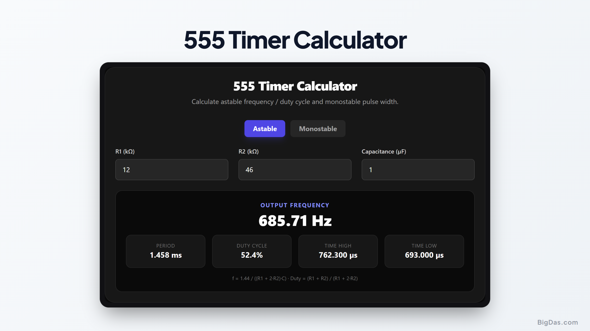
555 Timer Calculator
 Generated infographic and interface snapshot for 555 Timer Calculator
Design astable and monostable 555 circuits without the algebra.
Free 555 Timer Calculator Online. Big Das
The 555 timer IC has been around since 1972. It runs LED blinkers, PWM motor drivers, tone generators, and a lot more. The Big Das 555 Timer Calculator computes frequency, period, and duty cycle for astable mode, or pulse width for monostable mode, from your resistor and capacitor values.
Enter R1, R2, and C. The results update live in your browser.
What Is a 555 Timer?
The 555 timer is an 8-pin IC that works as an oscillator, timer, or flip-flop. Two configurations cover most uses:
- Astable mode outputs a continuous square wave. Common in clocks, tone generators, and LED flashers.
- Monostable mode outputs a single pulse of fixed duration on trigger. Common in switch debouncing and delay generation.
External resistors and a capacitor set the timing. That makes the 555 flexible, but it also means you need some math to hit a target frequency or pulse width.
Astable Mode
In astable configuration, the capacitor charges through R1 and R2, then discharges through R2 alone. The output oscillates freely. Frequency and duty cycle come from the resistor ratio.
Monostable Mode
In monostable configuration, a trigger pulse starts a single timing cycle. The output stays high for a duration set by one resistor and one capacitor, then returns low until the next trigger.
How to Use the 555 Timer Calculator
- Select the mode: click Astable or Monostable at the top.
- Enter R1 (kΩ): For astable, this is the resistor between Vcc and the discharge pin. For monostable, this is the timing resistor.
- Enter R2 (kΩ): Astable only: the resistor between the discharge pin and the threshold/trigger pins.
- Enter Capacitance (µF): The timing capacitor connected to ground.
- Read the results: Frequency, period, duty cycle, and high/low times appear instantly for astable mode; pulse width appears for monostable mode.
The Formulas Used
Astable Mode
- Frequency:
f = 1.44 / ((R1 + 2 × R2) × C) - Period:
T = 1 / f - Time high:
T_high = 0.693 × (R1 + R2) × C - Time low:
T_low = 0.693 × R2 × C - Duty cycle:
Duty = (R1 + R2) / (R1 + 2 × R2)
Monostable Mode
- Pulse width:
t = 1.1 × R × C
All resistances are in ohms and capacitances in farads before conversion to Hz and seconds.
Worked Example
Suppose you want a 1 kHz tone for a buzzer using astable mode:
- R1 = 1 kΩ
- R2 = 10 kΩ
- C = 0.1 µF
Convert to base units: R1 = 1000 Ω, R2 = 10,000 Ω, C = 0.0000001 F.
Frequency = 1.44 / ((1000 + 2×10,000) × 0.0000001) = 1.44 / (21,000 × 0.0000001) = 1.44 / 0.0021 ≈ 686 Hz
Not quite 1 kHz. Reducing R2 to about 6.8 kΩ gives roughly 1.06 kHz. The calculator lets you iterate instantly.
For monostable mode, a 10 kΩ resistor and 10 µF capacitor give:
Pulse width = 1.1 × 10,000 × 0.00001 = 0.11 seconds
Common Use Cases
- LED flashers: Generate a visible blink rate for indicators and toys.
- Tone generation: Drive a speaker or piezo buzzer with a square wave.
- Switch debouncing: Produce a clean single pulse from a noisy mechanical switch.
- PWM dimming: Control LED brightness or motor speed with a variable duty cycle.
- Time delays: Create a fixed delay after a trigger event, such as turning off a light.
Frequently Asked Questions
Why is the duty cycle always above 50% in astable mode?
Because the capacitor charges through R1 + R2 but discharges only through R2. The charge path is always longer than the discharge path. To approach 50%, make R1 much smaller than R2, or add a diode bypass.
What happens if I make R2 zero?
The formula breaks down, division by zero. In practice, the discharge pin would short the capacitor directly to ground, overheating the IC. The calculator flags R2 = 0 as an error to protect your design.
Can I use electrolytic capacitors?
Yes, especially for low frequencies. Be aware that electrolytics have wide tolerances (±20% is common) and leakage, so your actual frequency may differ from the calculated value more than with film or ceramic capacitors.
What voltage should I run the 555 at?
The classic NE555 works from 4.5 V to 15 V. The timing formulas are independent of supply voltage, which is one of the chip's great strengths.
How accurate are the formulas?
The constants 1.44 and 1.1 are rounded from ln(2) ≈ 0.693. The formulas assume an ideal 555, so real-world frequency can vary a few percent with temperature and component tolerance.
Can I calculate monostable pulse width in milliseconds?
Absolutely. Enter R in kΩ and C in µF, and the tool displays the result in ms, µs, or seconds automatically. A 10 kΩ resistor with 1 µF gives an 11 ms pulse.