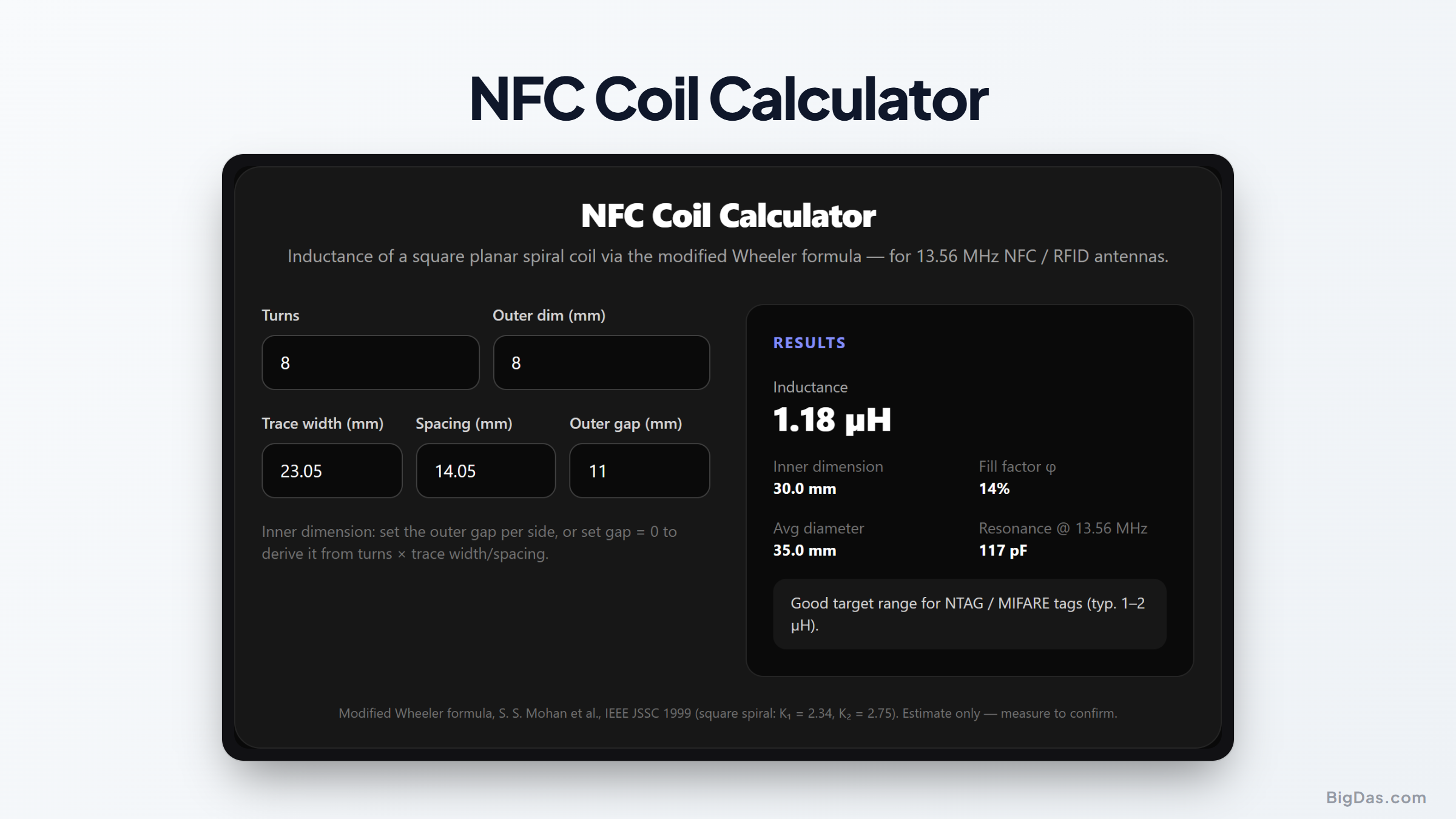
NFC Coil Calculator
 Generated infographic and interface snapshot for NFC Coil Calculator
Estimate 13.56 MHz loop-antenna inductance before you spin the board.
Free NFC Coil Calculator Online — Big Das
Designing a custom NFC or RFID reader antenna? The Big Das NFC Coil Calculator estimates the inductance of a square planar spiral coil from turns, dimensions, and trace geometry — using the modified Wheeler formula — so you can target the 1–2 µH sweet spot for NTAG and MIFARE tags.
Results update live: tweak turns or trace width and watch the inductance change.
What Is an NFC Coil?
Near-field communication at 13.56 MHz works by inductive coupling: a reader generates an alternating magnetic field, and a tag nearby harvests energy and communicates by load modulation. Both sides use a planar spiral coil etched on PCB or copper wire.
Reader coils are larger (30–60 mm) and run at low inductance so matching networks stay easy.
Tag coils are small (often under 30 mm) and must still reach enough inductance to resonate with tens of picofarads.
The critical design number is inductance L, because the matching network is tuned for
L ≈ 1–2 µHat 13.56 MHz.
How to Use the NFC Coil Calculator
- Turns — the number of spiral loops (typically 2–6 for small coils).
- Outer dimension (mm) — the square coil's outer edge length.
- Trace width and spacing (mm) — controlled by your PCB fab's limits (0.15 mm is common).
- Outer gap (mm) — clearance between the outermost trace and the coil's bounding box; set to 0 to derive the inner dimension from turns × trace geometry instead.
- Read the results — inductance in µH, fill factor, average diameter, and the capacitance that would self-resonate the coil at 13.56 MHz.
The Formula Used
The coil is approximated with the modified Wheeler formula for a square spiral, as tabulated by S. S. Mohan et al. (IEEE J. Solid-State Circuits, 1999):
dAvg = (dOut + dIn) / 2
φ    = (dOut − dIn) / (dOut + dIn)            (fill factor)
L    = K1 · µ0 · n² · dAvg / (1 + K2 · φ)

square spiral: K1 = 2.34, K2 = 2.75
µ0 = 4π × 10⁻⁷ H/m
Distances are in metres before conversion to µH; dimensions entered in mm are converted automatically.
Worked Example
A 40 mm × 40 mm PCB coil with 4 turns, 0.5 mm trace, and a 5 mm outer gap per side:
dIn  = 40 − 2 × 5 = 30 mm
dAvg = (40 + 30) / 2 = 35 mm = 0.035 m
φ    = (40 − 30) / (40 + 30) ≈ 0.143
L    = 2.34 × 4π×10⁻⁷ × 16 × 0.035 / (1 + 2.75 × 0.143)
≈ 1.18 µH
That's right in the 1–2 µH window that matches NTAG2xx / MIFARE Ultralight tags well. At 13.56 MHz, self-resonance with a bare coil would need only ~117 pF — comfortably above typical parasitics.
Common Use Cases
- Custom NFC reader antennas for point-of-sale terminals and access control.
- PCB antenna design before simulation, to scope the search space.
- Badge and card form factors where coil area is fixed and turns must be traded off against trace width.
- Antenna matching as a starting point: once L is known, the balance of a pi-network (typically 33–100 pF + resistor per branch) can be computed.
Frequently Asked Questions
How accurate is the modified
Wheeler formula?
For square spirals with a fill factor between roughly 0.1 and 0.9 it is typically within 5–10% of a fabricated PCB measurement, which is good enough for initial matching design. Always confirm with an LCR meter or VNA before committing to a layout.
Why do most 13.56 MHz designs target 1–2 µH?
Lower inductance keeps matching capacitors large enough to tune but small enough to miniaturise, and detunes less when a phone hovers nearby. Above ~3 µH, tiny capacitance changes swing the match noticeably.
What's a sensible trace width and spacing for FR4?
0.15–0.3 mm is the comfort zone of most PCB fabs. Very fine pitch (≤0.1 mm) raises copper cost and lowers Q; keep your turn count moderate instead.
Does this work for circular coils?
Use the same formula with K1 = 2.5, K2 = 3.55 and the coil diameters. The square coefficients here are for the much more common rectangular NFC loop.
Can I use multilayer coils?
Yes — inductances of turns in series on stacked layers add roughly as the square of total turns, so this estimator still applies if you treat it as one coil with more turns. Watch inter-layer capacitance though: it shifts self-resonance down.
Does the ferrite sheet matter?
Yes — a ferrite backing behind the coil (mandatory when mounting on metal) increases inductance by roughly 30–100% depending on the material. Design the bare coil 10–20% under target, then measure on the final stack-up.