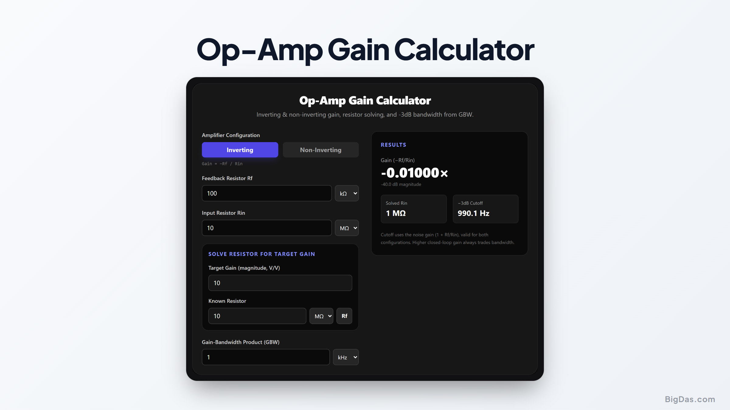
Op-Amp Gain Calculator
 Generated infographic and interface snapshot for Op-Amp Gain Calculator
Design inverting and non-inverting op-amp circuits in seconds.
Free Op-Amp Gain Calculator Online — Big Das
The operational amplifier is the workhorse of analog electronics. Whether you are building an audio preamp, a sensor signal conditioner, or an active filter, the very first design decision is always the same: *how much gain do I need, and which resistors get me there?
- Our free Op-Amp Gain Calculator answers both questions instantly — and tells you the bandwidth your gain actually costs you.
What Is an Op-Amp Gain Calculator?
An op-amp gain calculator computes the relationship between resistor values and closed-loop gain for the two classic amplifier topologies:
- Inverting amplifier — the input signal is applied through Rin to the inverting (−) input; the output is inverted.
- Non-inverting amplifier — the input drives the non-inverting (+) input directly; the output keeps its polarity.
Because the op-amp's open-loop gain is enormous (typically 100 dB or more), the final closed-loop gain is set almost entirely by the two external resistors — not by the chip itself. That makes the math simple, predictable, and exactly the kind of thing a calculator should do for you.
How to Use the Tool
- Choose the configuration — Inverting or Non-Inverting.
- Enter Rf and Rin/R1 with their units (Ω, kΩ, or MΩ). The gain updates live.
- Solve a resistor for a target gain — enter your desired gain and one known resistor; the tool computes the missing value.
- Enter the op-amp's Gain-Bandwidth Product (GBW) from its datasheet to see the resulting −3dB cutoff frequency.
The Formulas
- Inverting gain:
A = −Rf / Rin - Non-inverting gain:
A = 1 + Rf / R1 - Solve Rf for a target non-inverting gain G:
Rf = R1 × (G − 1) - Solve R1:
R1 = Rf / (G − 1)— for inverting, simplyRin = Rf / G. - −3dB cutoff frequency:
fc = GBW / (1 + Rf / Rin)
Note the last formula carefully: the bandwidth depends on the noise gain (1 + Rf/Rin), not the signal gain. This is why an inverting amplifier of gain −10 and a non-inverting amplifier of gain +11 have the same bandwidth.
Worked Example
You need an inverting preamp with a gain of −10 using an op-amp rated at 1 MHz GBW. Pick Rf = 100 kΩ, so Rin = Rf / G = 100 kΩ / 10 = 10 kΩ. The calculator shows:
Gain: −10 V/V (20 dB)
Noise gain: 1 + 100/10 = 11
−3dB cutoff: 1 MHz / 11 ≈ *90.9 kHz
Had you built the same circuit non-inverting, the gain would be +11, not +10 — a classic trap for beginners, and a good reason to double-check with a calculator before soldering.
Common Use Cases
- Audio design: microphone preamps, mixers, tone-control stages, and guitar pedals.
- Sensor interfaces: amplifying millivolt-level signals from thermocouples, strain gauges, and photodiodes before an ADC.
- Active filters: setting passband gain in Sallen-Key and multiple-feedback topologies.
- Education: verifying lab exercises and homework calculations in analog electronics courses.
Frequently Asked Questions
Can the non-inverting amplifier have a gain less than 1?
No. The formula 1 + Rf/R1 has a minimum of 1 (unity gain), reached when Rf is zero or R1 is open. For attenuation you need an inverting stage or a passive divider. The tool flags this case automatically.
Why does higher gain reduce bandwidth?
The op-amp's gain-bandwidth product is constant. Closing the loop with a higher feedback factor forces the closed-loop gain down, and the frequency where loop gain runs out moves down with it: fc = GBW / noise gain.
Is the −3dB cutoff the same for inverting and non-inverting?
Only at the same noise gain. The noise gain is 1 + Rf/Rin for both topologies, so an inverting gain of −9 and a non-inverting gain of +10 share the same bandwidth.
What resistor values are practical?
Typical designs keep Rf between about 1 kΩ and 1 MΩ. Very small resistors load the output stage; very large ones add Johnson noise and make the circuit sensitive to bias currents and PCB leakage.
Does this work for single-supply circuits?
Yes — the gain formulas are unchanged. Single-supply operation only adds a biasing network (usually a Vcc/2 reference) that doesn't enter the AC gain calculation.
What about input and output impedance?
An inverting amplifier's input impedance equals Rin, while the non-inverting input impedance is very high (the op-amp's own input impedance). Both have very low output impedance within the passband.