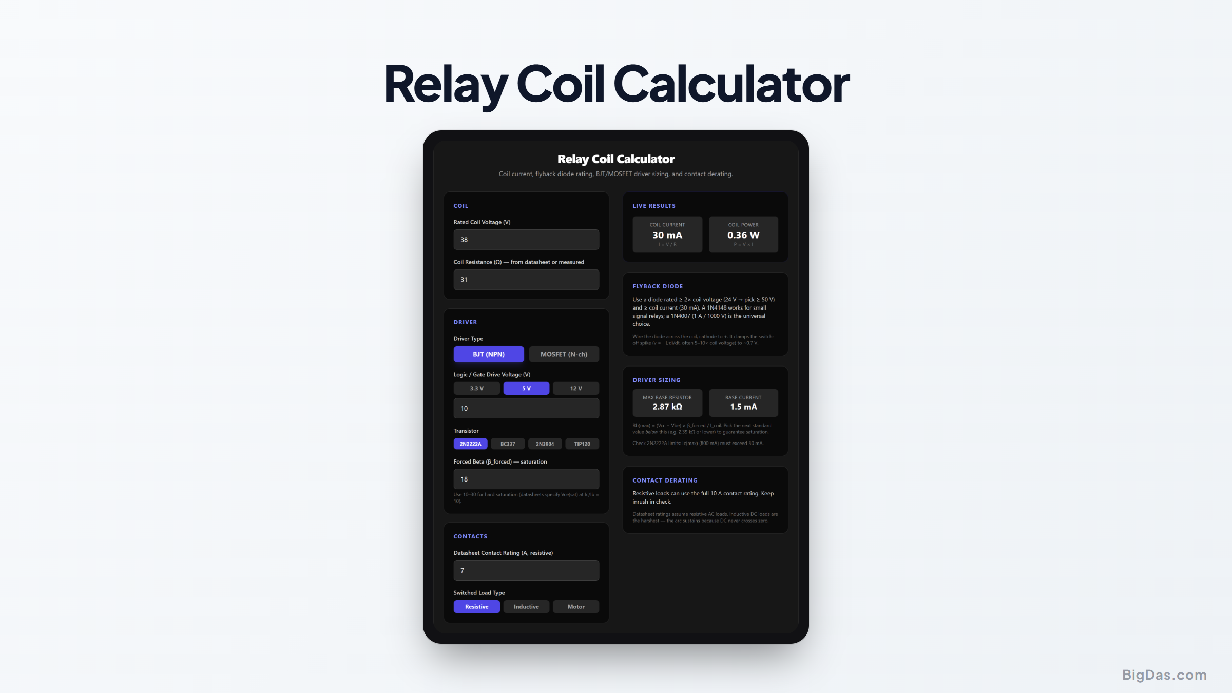
Relay Coil Calculator
 Generated infographic and interface snapshot for Relay Coil Calculator
Size the coil driver, flyback diode, and base resistor before you solder anything.
Free Relay Coil Calculator Online — Big Das
Driving a relay from a microcontroller is one of the first real "power electronics" jobs most builders face — and one of the easiest to get subtly wrong. The Big Das Relay Coil Calculator takes the datasheet coil voltage and resistance and returns everything you need: steady coil current and power, a flyback diode rating, base-resistor sizing for an NPN driver (or MOSFET guidance), and a contact derating check for the load you are actually switching.
Everything runs in your browser and updates live as you type.
What Is a Relay Coil Circuit?
An electromagnetic relay is two devices in one: a coil that acts as an inductor and must be driven with enough current to pull the armature in, and contacts that switch your real load. Each side has its own failure modes:
- Undersized driver — the transistor drops voltage instead of saturating, the coil sees less than its rated voltage, and the relay chatters or never pulls in.
- Missing flyback diode — when the coil switches off, its stored energy slams the driver with a voltage spike (v = −L·di/dt) that can exceed ten times the supply and kill the transistor.
- Ignorant contact derating — a "10 A" relay is only 10 A into a resistive load; a motor or solenoid can weld those contacts in weeks.
How to Use the Relay Coil Calculator
- Enter the rated coil voltage (V) — usually printed on the relay: 5, 12, or 24 V.
- Enter the coil resistance (Ω) — from the datasheet, or measure it with a multimeter across the coil pins.
- Pick the driver type — BJT (NPN) or N-channel MOSFET.
- Set the logic voltage — 3.3 V, 5 V, or 12 V, whatever drives the base/gate.
- For a BJT, choose the transistor and a forced beta (10–30 for hard saturation).
- Enter the datasheet contact rating and load type (resistive / inductive / motor) to see the derated limit.
- Read the results panel — coil current, power, diode guidance, base resistor, and derating note update live.
The Formulas Used
Coil current:        I_coil = V_rated / R_coil          (Ohm's law)
Coil power:          P_coil = V_rated × I_coil
Base resistor (max): Rb = (V_logic − V_be) × β_forced / I_coil
Base current:        Ib = I_coil / β_forced
Flyback diode:       rated ≥ 2× coil voltage, ≥ I_coil
Contact derating:    resistive 100%, inductive ~40%, motor ~20%
V_be is 0.7 V for a single BJT, 1.4 V for a Darlington. Forced beta is deliberately much lower than the datasheet hFE — transistors are characterised for saturation at Ic/Ib = 10, so designing with β_forced = 20 leaves real margin.
Worked Example
A common sugar-cube relay with a 12 V, 400 Ω coil, driven from a *5 V
- GPIO through a 2N2222A with β_forced = 20:
Coil current = 12 / 400 = 30 mA
Coil power = 12 × 0.03 = 0.36 W
Rb(max) = (5 − 0.7) × 20 / 0.03 = 2867 Ω → pick 2.2 kΩ to stay safely in saturation
Base current = 30 / 20 = 1.5 mA — trivial for any MCU pin
Flyback diode: 30 mA and 12 V → a 1N4148 suffices, but a 1N4007 is the universal drawer part
If that relay's contacts are rated 10 A resistive and you switch a motor, the calculator derates to ~2 A — a useful early warning.
Common Use Cases
- Arduino / ESP32 relay modules — verify the on-board transistor and diode suit a replacement relay.
- Automotive accessories — 12 V coils switching fans, horns, or lighting with proper derating.
- Industrial control panels — 24 V contactor coils interlocked through pilot relays.
- Retrofitting — measure the coil of an unmarked relay and get a safe driver design instantly.
Frequently Asked Questions
Can I drive a small relay directly from a GPIO pin?
Only if the coil current is under the pin's rating (often 20 mA) — which rules out most power relays. A 5 V / 70 Ω reed-style coil drawing 71 mA already needs a transistor. When in doubt, use the driver.
Why forced beta instead of datasheet hFE?
Datasheet hFE is measured in the linear region. In saturation (what a switch needs), gain collapses, and manufacturers spec Vce(sat) at Ic/Ib = 10. Designing for β_forced of 10–30 guarantees the transistor acts as a switch, not a heater.
Does the flyback diode slow the relay release?
Yes — the coil current circulates through the diode and decays slowly. For faster drop-out, add a Zener in series with the diode (Zener voltage below the transistor's rating), which dissipates the stored energy faster.
Why do motor loads derate so hard?
A motor's locked-rotor / starting current is 6–10× its running current, and opening contacts on that current draws an arc with no zero-crossing on DC. The 20% derating rule keeps make-and-break stress inside the contact material's capability.
What if I use a MOSFET instead?
Easier: pick a logic-level MOSFET whose Rds(on) is specified at your gate voltage, and you skip the base-resistor math entirely. You still need the flyback diode — the MOSFET's body diode does not clamp the drain spike.