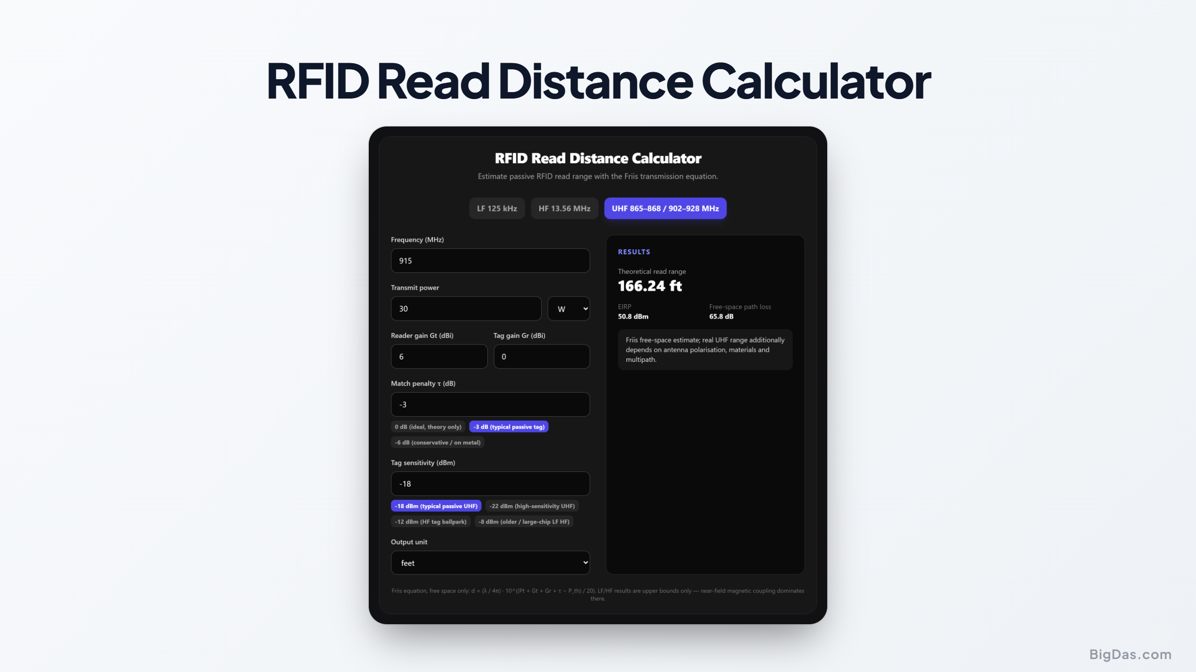
RFID Read Distance Calculator
 Generated infographic and interface snapshot for RFID Read Distance Calculator
Estimate passive RFID read range from a handful of link-budget numbers.
Free RFID Read Distance Calculator Online — Big Das
How far will that UHF tag actually read? The Big Das RFID Read Distance Calculator applies the Friis transmission equation in free space — reader power and antenna gain, tag gain, matching loss, and chip sensitivity — and returns the maximum theoretical range with sensible presets for LF, HF, and UHF.
What Determines RFID Read Range?
A passive RFID tag has no battery: it harvests energy from the reader's radio field, then backscatters data by modulating its radar cross-section. Read distance is therefore a link-budget question, limited by whichever is worse — powering the chip forward, or hearing the scatter back.
- UHF (865–928 MHz) systems are far-field and governed by the Friis equation: range scales with the square root of effective radiated power.
- HF (13.56 MHz) and LF (125 kHz) work by inductive near-field coupling; Friis does not apply — it only gives an optimistic upper bound, and real HF/NFC reads are typically under 10 cm.
This calculator models the forward link (reader → chip power-up), the usual limiting case.
How to Use the Calculator
- Pick a band preset — LF 125 kHz, HF 13.56 MHz, or UHF 865/915 MHz — or enter any frequency directly.
- Transmit power — in dBm or watts (4 W ERP ≈ 30 dBm conducted + 6 dBi antenna).
- Antenna gains — reader Gₜ and tag Gᵣ in dBi (0 dBi is a typical small dipole-like tag).
- Match penalty τ — 0 dB is ideal; −3 dB is realistic for a good passive tag; −6 dB is conservative (on-metal or detuned).
- Tag sensitivity — −18 dBm is a typical modern UHF chip (Impinj Monza class); −22 dBm is high-sensitivity; LF/HF chips are typically −8 to −12 dBm.
- Read the range — in metres, feet, or kilometres, with EIRP and free-space path loss shown alongside.
The Formula
λ            = c / f
Pr (dBm)     = Pt + Gt + Gr + τ − 20·log10(4πd/λ) − 30
solving for d:

d = λ/(4π) · 10^( (Pt + Gt + Gr + τ − Pth) / 20 )
All powers in dBm, gains in dBi, τ and P_th in dB / dBm. Because the range appears in the path-loss term, every 6 dB of link budget doubles the distance.
Worked Example
A warehouse UHF reader at 915 MHz, 30 dBm (1 W) conducted power into a 6 dBi circular antenna, tag with Gr = 0 dBi, τ = −3 dB, sensitivity P_th = −18 dBm:
λ           = 3×10⁸ / 915×10⁶  ≈ 0.328 m
margin      = 30 + 6 + 0 − 3 − (−18) = 51 dB
d           = 0.328/(4π) × 10^(51/20)
≈ 0.0261 × 355
≈ 9.25 m  (≈ 30 ft)
That matches real-world ceiling-mounted UHF portals reading passive carton labels at about 9–10 m in open space. Moving the tag onto metal without a proper on-metal design (−6 dB τ) drops the range to ~6.5 m.
Use Cases
- Site surveys: choose antenna and power combos before installing a warehouse portal.
- Tag selection: compare chip generations (−18 dBm vs −22 dBm sensitivity = ~1.6× range).
- Regulatory checks: see exactly what EIRP your antenna produces at a given conducted power.
- Education: understand why doubling reader power only gives √2 more range.
Frequently Asked Questions
Why is my real UHF range shorter than the calculator?
Friis assumes free space and perfect polarisation. Concrete floors, metal shelving, linear polarisation mismatch (3 dB), and body blocking each chip away. Multipath can occasionally add range indoors, but plan for 60–80% of the free-space number in open warehouses.
The LF result says 16 km — is that right?
No — that's Friis operating far outside its validity. LF and HF tags are near-field magnetically coupled; useful ranges are millimetres to tens of centimetres. The calculator flags LF/HF outputs as upper bounds precisely because the far-field 1/d² model doesn't apply to a coupled-coil system that falls off roughly as 1/d³.
What is the match penalty τ?
The tag antenna and chip rarely present a perfect conjugate match. τ accounts for the lost power, typically 2–3 dB on a good broadband dipole label, worse for on-metal or die-cut tags tuned for a different region.
Does backscatter matter for the read distance?
Often it's the forward link that fails first: the chip needs to wake up before it can talk back. But very low backscatter cross-sections (small or metal-mounted tags) can flip the limiting link to the return path, shortening real range.
Can I use ERP instead of EIRP?
Yes — just remember ERP = EIRP − 2.15 dB. Entering 30 dBm with a 6 dBi antenna yields 36 dBm EIRP, the FCC US limit (4 W EIRP); Europe's ETSI limit is 2 W ERP ≈ 33 dBm EIRP, so use ~27 dBm + 6 dBi there.