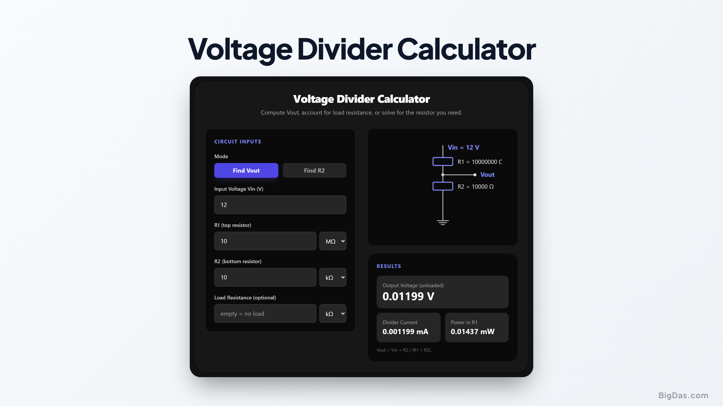
Voltage Divider Calculator
 Generated infographic and interface snapshot for Voltage Divider Calculator
Divide any voltage down safely — with or without a load attached.
Free Voltage Divider Calculator Online — Big Das
The voltage divider is the most-used circuit in electronics: two resistors in series that produce an output voltage proportional to their ratio. Whether you are scaling a 12 V battery down to 3.3 V for a sensor, biasing a transistor, or generating a reference voltage for an ADC, the math is always the same — and it is easy to get wrong when a load is attached.
The Big Das Voltage Divider Calculator runs the classic formula live in your browser, computes the loaded-divider output when a real circuit is connected, and can even solve backwards: tell it your target output and it tells you which resistor to use.
What Is a Voltage Divider?
A voltage divider is two resistors in series across a voltage source. The junction between them — the output node — sits at a fraction of the input voltage set by the resistor ratio:
- R1 is the "top" resistor, between Vin and the output node.
- R2 is the "bottom" resistor, between the output node and ground.
As long as nothing (or almost nothing) draws current from the output, the output voltage is a simple function of the two resistances. Attach a load, though, and the effective lower resistance changes — which is why this calculator handles both cases.
Unloaded vs. Loaded Dividers
An unloaded divider assumes the loads draws no current. In practice every ADC pin, transistor base, or sensor adds some resistance to the output node. That load lands in parallel with R2, forming R2‖RL, and drags Vout down. This tool shows both values side by side so you can see exactly how much sag to expect.
How to Use the Voltage Divider Calculator
- Choose the mode — Find Vout to compute the output from known resistors, or Find R2 to solve for the resistor you need.
- Enter Vin — the supply voltage across the divider.
- Enter R1 with its unit (Ω, kΩ, or MΩ).
- Enter R2 (Find Vout mode) or your target Vout (Find R2 mode).
- Optionally enter a load resistance — leave empty for an ideal, unloaded divider.
- Read the results — Vout updates live, including the divider current, the power dissipated in R1, and the sag caused by any load.
The Formulas Used
- Unloaded divider:
Vout = Vin × R2 / (R1 + R2) - Loaded divider:
R2eff = R2 × RL / (R2 + RL), thenVout = Vin × R2eff / (R1 + R2eff) - Solve for R2:
R2 = R1 × Vout / (Vin − Vout) - Divider current:
I = Vin / (R1 + R2eff) - Power in R1:
P = I² × R1
Worked Example
You want to sample a 12 V battery with a 3.3 V ADC input. Try R1 = 10 kΩ and R2 = 3.9 kΩ:
Vout = 12 × 3900 / (10000 + 3900) = 12 × 3900 / 13900 ≈ 3.37 V — slightly high at full charge; bump R2 to 3.6 kΩ for 3.18 V, comfortably within range.
Divider current = 12 / 13,600 ≈ 0.88 mA, so the divider itself won't meaningfully drain the battery.
Now check the load: if your ADC input moldels as 100 kΩ, R2‖RL = 3,600 × 100,000 / 103,600 ≈ 3,474 Ω, and Vout sags to about 3.10 V — a 1.3% error you might need to calibrate out.
Common Use Cases
- ADC input scaling: Bring battery or sensor voltages inside a 1.8/3.3/5 V converter range.
- Reference voltages: Generate intermediate voltages for op-amp and comparator circuits.
- Transistor biasing: Set the base voltage of a BJT amplifier stage.
- Level shifting (light-duty): Approximate 5 V → 3.3 V translation for slow digital lines.
- Voltage monitoring: Detect power-good thresholds with a comparator and a divider tap.
Frequently Asked Questions
Why does my measured
Vout differ from the ideal value?
Two main reasons: resistor tolerance (±5% resistors can each shift the ratio) and loading. If the circuit you connect draws current, it parallels R2 and pulls Vout down — enter your load in the tool to model it.
How do I pick resistor magnitudes?
Lower values waste more power but are stiffer against loading; higher values save power but are sensitive to load and noise. A common compromise is divider currents of 0.1–1 mA for battery circuits, or 1–10 mA where stiffness matters.
What happens if R2 is larger than R1?
Nothing bad — Vout just rises above half of Vin. Vout always stays below Vin; the ratio R2/(R1+R2) can never reach or exceed 1.
Can a voltage divider power a circuit?
Not directly. Any meaningful load current changes the divider ratio and sags the output. Use a linear regulator, buck converter, or buffer the divider with an op-amp instead.
What is the nearest standard resistor to my solved value?
The Find R2 mode shows the nearest E24-series value. E24 covers the standard ±5% resistor line; for tighter matching pick E96 (1%) parts or use a series/parallel combination.
Is there a maximum Vin?
Electrically the divider works at any voltage, but mind the power rating of R1 (P = I²R) and never use a divider to touch mains voltage — use proper isolation components instead.