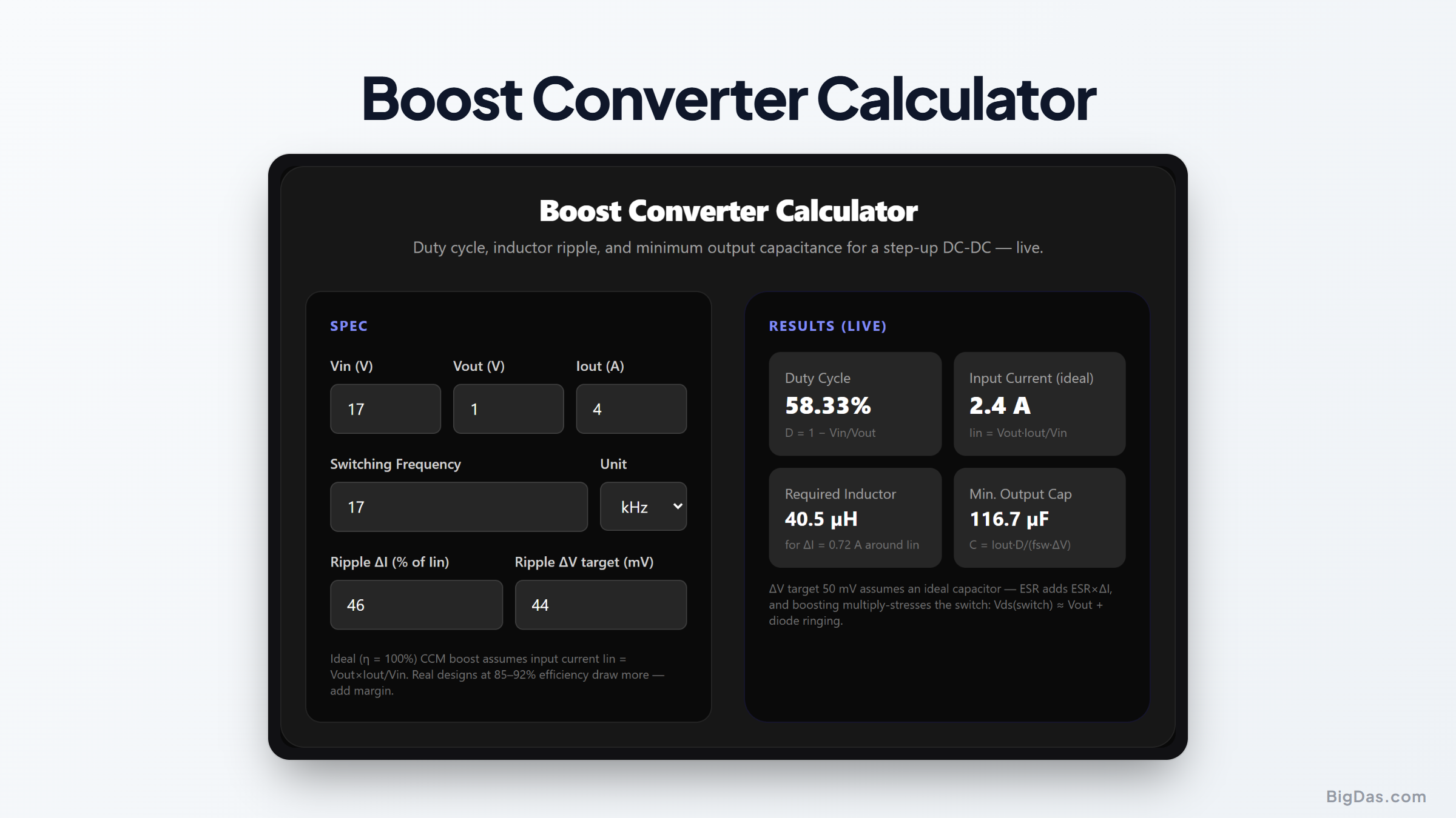
Boost Converter Calculator
 Interface snapshot for the Boost Converter Calculator
Step up a voltage without blowing the inductor ripple budget.
Free Boost Converter Calculator. Big Das
Need 12 V from a 5 V rail, or 24 V from a lithium pack? The Big Das Boost Converter Calculator gives you duty cycle, inductor value for a target current ripple, minimum output capacitance, and a practical-limit warning when the required duty cycle exceeds 90 %.
What Is a Boost Converter?
A boost (step-up) converter stores energy in an inductor while the switch is on, then releases it in series with the input when the switch opens. The output sits above the input. It's the mirror image of a buck and is necessary for battery-powered gear that needs a rail higher than the pack voltage.
Unlike a buck, the boost's output diode disconnects the load from the source unless the switch is off. This creates pulsed output current and demands more output capacitance for the same ripple.
How to Use the Calculator
- Enter Vin and Vout: the tool enforces Vout > Vin for a boost.
- Enter the load current Iout.
- Set the switching frequency (100 kHz, 1 MHz is typical for discrete designs).
- Set the inductor ripple target as a percentage of the input current (which is larger than Iout).
- Set the output ripple target in mV to size the minimum output capacitor.
- Read the duty cycle, inductor, input current, and capacitor, with a warning if duty exceeds 90 %.
The Formulas Used
Duty cycle: D = 1 − Vin / Vout (Vout/Vin = 1/(1−D))
Input current: Iin = Vout × Iout / Vin (ideal, η = 100%)
Inductor: L = Vin × D / (fsw × ΔI)
Ripple target: ΔI = ripple% × Iin
Output capacitor: C ≥ Iout × D / (fsw × ΔV)
These are the standard CCM boost relations from Erickson & Maksimović, Fundamentals of Power Electronics, and most vendor application notes (TI SLVA061, Analog Devices app briefs).
Worked Example
5 V to 12 V at 1 A, 100 kHz, 30 % input-current ripple, 50 mV output ripple target.
- Duty: 1 − 5/12 = 58.3 %
- Input current: 12 × 1 / 5 = 2.4 A
- ΔI target: 0.30 × 2.4 = 0.72 A
- Inductor: 5 × 0.583 / (100,000 × 0.72) ≈ 40.5 µH → choose 47 µH
- Min. capacitance: 1 × 0.583 / (100,000 × 0.05) = 116.7 µF → choose 150 µF or larger
Duty is well under 90 %, so this is a comfortable single-stage boost.
Common Use Cases
- Generating a 12 V analog rail from a 5 V USB supply.
- Boosting a single Li-ion cell (3 to 4.2 V) to 5 V for peripherals.
- LED string drivers from a lower-voltage bus.
- Checking effort before choosing between boost, SEPIC, or flyback.
Frequently Asked Questions
Why is input current higher than output current?
Power (minus losses) is conserved: Pin ≈ Pout, so Iin = Vout×Iout/Vin. Boosting 5 V to 12 V at 1 A draws at least 2.4 A from the source, at 85 % efficiency, about 2.8 A.
Why does the calculator warn above 90 % duty?
Real boosts can't deliver infinite gain. As D approaches 1, parasitic resistance and switch losses cause the ideal 1/(1−D) curve to roll off; efficiency crashes, inductor RMS current soars, and compensation becomes nearly impossible. Many boost ICs hard-limit duty to 85 to 95 %.
Can I use this for SEPIC or buck-boost?
No. A SEPIC or inverting buck-boost uses D/(1−D) and has different capacitor and inductor stresses. This tool covers only the non-inverting boost where Vout > Vin.
Why is the output ripple formula different from a buck's?
In a boost, the output capacitor alone supplies the load during the entire on-time (D×T), so C = Iout·D/(fsw·ΔV). A buck's inductor feeds the load continuously, giving the gentler ΔI/(8·fsw·C) law.
What limits real-world boost voltage?
Switch voltage rating (must exceed Vout), diode rating, inductor saturation current (peak = Iin + ΔI/2), and the control IC's maximum duty and compensation range.