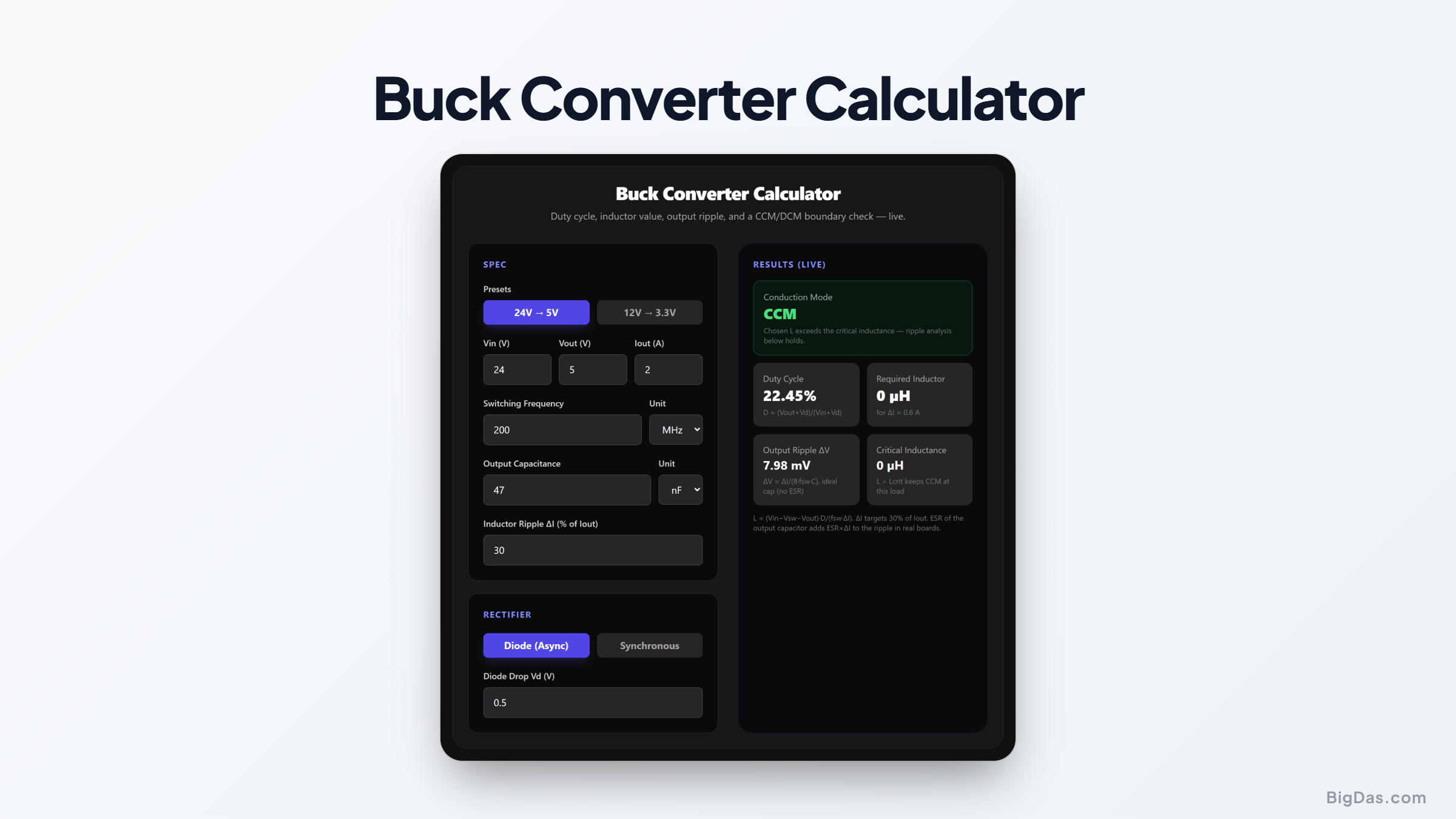
Buck Converter Calculator
 Generated infographic and interface snapshot for Buck Converter Calculator
Size the inductor and capacitor before you burn the board.
Free Buck Converter Calculator Online. Big Das
The buck (step-down) converter is a common DC-DC topology. The Big Das Buck Converter Calculator computes duty cycle, required inductor, output voltage ripple, and whether the design stays in continuous conduction mode, with switch/diode drop corrections and presets like 24 V → 5 V.
What Is a Buck Converter?
A buck converter chops the input voltage with a high-side switch, then smooths the result through an inductor and capacitor to produce a lower, regulated output. It's more efficient than a linear regulator because the switch is either fully on or fully off, almost never dissipating power in between.
The two main design questions:
- How large must the inductor be to keep current ripple at the target (typically 20 to 40 % of load current)?
- Is the converter in CCM or DCM?
Continuous conduction mode is predictable; discontinuous mode changes the transfer function and raises ripple.
How to Use the Calculator
- Pick a preset (24 V → 5 V or 12 V → 3.3 V) or type your own Vin and Vout.
- Enter the load current in amps.
- Set the switching frequency: modern buck ICs run from 100 kHz to several MHz.
- Set the ripple target as a percentage of Iout; 30 % is a common starting point.
- Enter the output capacitance to see the resulting voltage ripple.
- Choose the rectifier: async (diode drop) or synchronous (MOSFET drop), to refine the duty cycle.
The Formulas Used
Duty (async diode): D = (Vout + Vd) / (Vin + Vd)
Duty (synchronous): D = Vout / (Vin − Vsw)
Inductor: L = (Vin − Vsw − Vout) × D / (fsw × ΔI)
Ripple target: ΔI = ripple% × Iout
Output ripple: ΔV = ΔI / (8 × fsw × Cout)
CCM/DCM boundary: Lcrit = (1 − D) × Vout / (2 × fsw × Iout)
If the chosen L is greater than Lcrit, the converter runs in continuous conduction mode at full load.
Worked Example: 24 V to 5 V at 2 A, 200 kHz, 30 % ripple, 47 µF output cap, async diode with 0.5 V drop
- Duty: (5 + 0.5) / (24 + 0.5) = 5.5 / 24.5 ≈ 22.45 %
- ΔI target: 0.30 × 2 = 0.6 A
- Inductor: (24 − 5) × 0.2245 / (200,000 × 0.6) ≈ 35.5 µH → pick 33 µH or 39 µH
- Output ripple: 0.6 / (8 × 200,000 × 47e-6) ≈ 8 mV (ideal capacitor)
- Lcrit: (1 − 0.2245) × 5 / (2 × 200,000 × 2) ≈ 4.8 µH, well below 35 µH, so the design is firmly CCM.
Common Use Cases
- Point-of-load rails for microcontrollers, FPGAs, and sensors.
- USB-C PD or barrel-jack input stepped down to system logic voltage.
- Choosing between a 100 kHz chunky-inductor design and a 2 MHz compact one.
- Sanity-checking a reference design's inductor before copying it onto the PCB.
Frequently Asked Questions
Why does 30 % ripple current come up so often?
It's a sweet spot: higher ripple shrinks the inductor but increases conduction loss, output ripple, and EMI; lower ripple needs a bigger, slower inductor. 20 to 40 % of full load is the classic compromise.
What changes between async and synchronous?
An async buck's catch diode drops ~0.3 to 0.7 V, so the duty cycle must stretch slightly to compensate, and the diode burns power at high currents. A synchronous (MOSFET) rectifier drops much less, improving efficiency, especially at low output voltages.
My calculated ripple is small but my scope shows huge spikes, why?
The formula assumes an ideal capacitor. Real electrolytics and even ceramics have ESR (and ESL) that add an ESR×ΔI ripple component, plus switching spikes from layout parasitics. Use low-ESR ceramics close to the IC.
What happens in DCM?
Below the critical inductance, inductor current hits zero each cycle. The duty-cycle equation no longer holds, ripple grows, and the control loop's behavior changes. Many buck ICs handle it gracefully, but ripple and efficiency estimates must be re-done for DCM.
Can I use this for a boost or buck-boost?
No, the transfer functions differ. Use the Big Das Boost Converter Calculator for step-up stages.