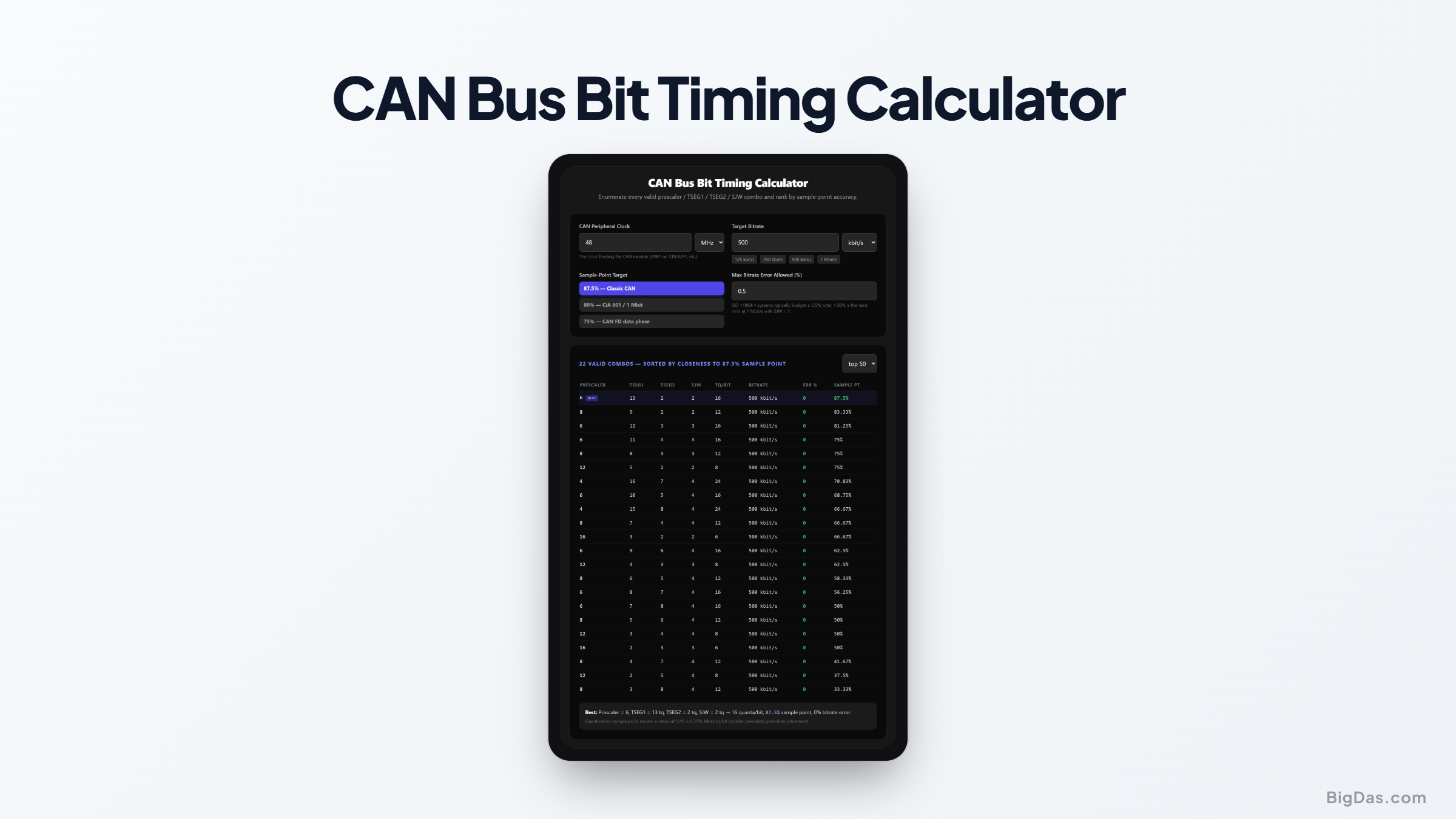
CAN Bus Bit Timing Calculator
 Generated infographic and interface snapshot for CAN Bus Bit Timing Calculator
Every valid prescaler / TSEG1 / TSEG2 / SJW combo, ranked by sample point.
Free CAN Bus Bit Timing Calculator Online. Big Das
Configuring a CAN controller means finding a prescaler and time-quanta split that hits your bitrate and lands the sample point where the bus needs it, usually 87.5% for classic CAN. The Big Das CAN Bus Bit Timing Calculator enumerates every legal (Prescaler, TSEG1, TSEG2, SJW) combination for your peripheral clock and target bitrate, computes the real bitrate, bitrate error, and sample point of each, and sorts them by closeness to your sample-point target.
No more trial-and-error in the reference manual's bit-timing register table.
What Is CAN Bit Timing?
Each CAN bit is divided into time quanta (tq), fixed slices derived from the peripheral clock through a prescaler:
- SyncSeg: always 1 tq; all nodes resynchronise here.
- TSEG1 (propagation + phase segment 1), signal travel time plus the sampling cushion, 2 to 16 tq.
- TSEG2 (phase segment 2), the resynchronisation margin after the sample point, 2 to 8 tq.
- SJW (synchronisation jump width), how far the edges can be pulled to resync, at most min(4, TSEG2) tq.
The bitrate is clock / (BRP × (1 + TSEG1 + TSEG2)), and the sample point sits at (1 + TSEG1) quanta into the bit.
How to Use the CAN Bus Bit Timing Calculator
- Enter the CAN peripheral clock: e.g. 48 MHz on an STM32F1 APB1, 8 MHz on an MCP2515 crystal.
- Enter the target bitrate: 125 / 250 / 500 kbit/s or 1 Mbit/s presets included.
- Choose the sample-point target: 87.5% (classic CAN), 80% (CiA 601), or 75% (CAN-FD data phase).
- Set the max bitrate error you can tolerate, 0.5% is a good system budget.
- Read the ranked table: best combo highlighted; prescaler, TSEG1, TSEG2, SJW, tq-per-bit, real bitrate, error %, and sample point are all shown.
The Formulas Used ```
Tq per bit: NBT = 1 + TSEG1 + TSEG2 (SyncSeg = 1 tq fixed) Bitrate: f = F_clock / (BRP × NBT) Sample point: SP = (1 + TSEG1) / NBT × 100% Bitrate error: err = |f_real − f_target| / f_target × 100% SJW limit: SJW ≤ min(4, TSEG2) Limits: BRP 1.1024, TSEG1 2.16, TSEG2 2.8
Every integer combination inside those limits that meets the error budget becomes a row in the table.

---

## Worked Example

An STM32F103 with a **48 MHz** CAN clock targeting **500 kbit/s**, sample point 87.5%:

- Try BRP = 8 → tq/bit = 48e6 / (8 × 500e3) = **12 tq**. Best split with TSEG2 ≥ 2: TSEG1 = 9, TSEG2 = 2 → SP = (1+9)/12 = **83.3%**. Works but shy of 87.5%.

- Try BRP = 4 → **24 tq/bit**. TSEG1 = 20, TSEG2 = 3 → SP = 21/24 = **87.5%** exactly, SJW = 3.

- Bitrate error in both cases is 0%, 48 MHz divides to 500 kHz exactly.

The optimal register values are BRP = 4, TS1 = 20, TS2 = 3, SJW = 3, the combo this calculator ranks first for the 87.5% target.

---

## Common Use Cases

- **STM32 bxCAN setup**: translate datasheet register fields into working timings.
- **MCP2515 (8/16 MHz crystal)**: find CNF1/CNF2/CNF3 values for Arduino CAN shields.
- **Vehicle retrofits**: sniffing a 33.3 kbit/s or 95.2 kbit/s bus needs exact oddball timings.
- **CAN FD**: check both arbitration (87.5%) and data-phase (75%) segments separately.

---

## Frequently Asked Questions

### Why is 87.5% the classic CAN sample point?

It is the CiA 301 / ISO 11898 convention for most bitrates: late enough to let the signal propagate the full bus, early enough to leave a full TSEG2 of resynchronisation margin. CiA 601 recommends 80% at 1 Mbit/s.

### What happens if two nodes use different sample points?

Both still sample within the bit, so moderate differences (a few percent) work. Large mismatches shrink the effective bus length and edge-rate tolerance, one node may sample ringing reflections.

### My clock doesn't divide exactly, how much error is tolerable?

ISO 11898-1 oscillator tolerance is typically 0.5% total for the network; 1.58% is the hard limit at 1 Mbit/s with SJW = 1. Prefer a crystal frequency that divides exactly.

### Should I prefer larger or smaller prescalers?

Smaller. More tq per bit gives finer sample-point granularity (1/24 ≈ 4.2% vs 1/12 ≈ 8.3% per quanta step) and looser oscillator tolerance.

### Does this work for CAN FD data phase?

The enumeration limits here are classic-CAN style (TSEG1 ≤ 16, TSEG2 ≤ 8). FD data-phase controllers extend these ranges, treat the 75% target results as a first guess, then confirm against your FD controller's wider register limits.