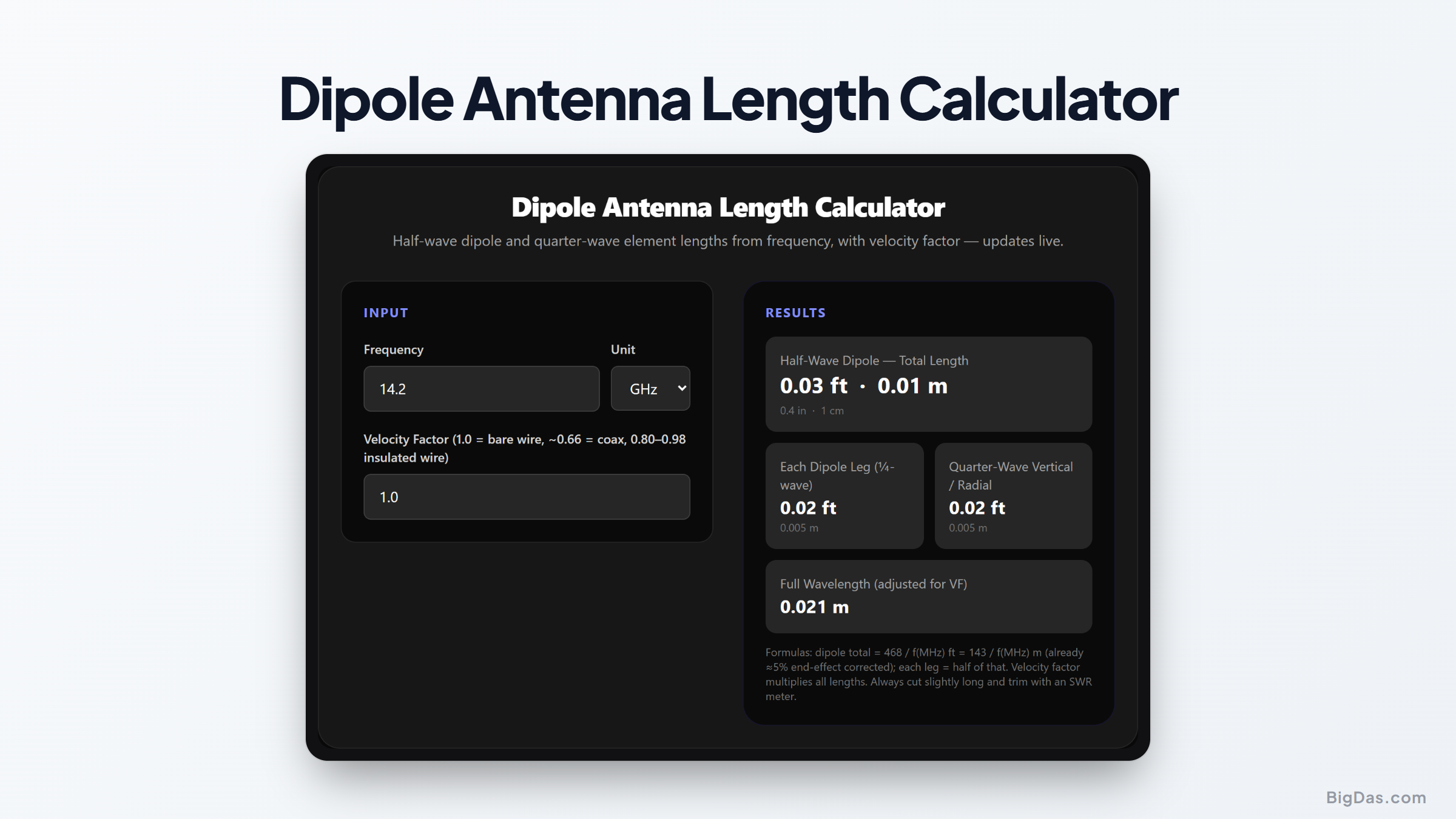
Dipole Antenna Length Calculator
 Generated infographic and interface snapshot for Dipole Antenna Length Calculator
Cut your half-wave dipole right the first time, with velocity factor correction.
Free Dipole Antenna Length Calculator Online. Big Das
The half-wave dipole is the most widely used antenna: two wires, one feed point, and reliable performance for everything from HF ham bands to FM broadcast reception. The catch is that it only performs when the lengths are right. The Big Das Dipole Antenna Length Calculator converts any operating frequency into the total dipole length and per-leg cut lengths, in feet, inches, meters and centimeters, with an adjustable velocity factor for insulated wire and non-ideal environments.
What Is a Half-Wave Dipole?
A dipole is a conductor split in the middle and fed at the gap, with each side measuring one quarter-wavelength. At its design frequency it presents a ~73 Ω resistive feed impedance and radiates efficiently in a broad figure-eight pattern. The closely related quarter-wave monopole (vertical) uses a single quarter-wave element over a ground plane, the calculator supplies those lengths too.
How to Use the Calculator
- Enter the center frequency with its unit. Hz through GHz. Example: 14.2 MHz for the 20-meter ham band.
- Set the velocity factor: leave it at 1.0 for the standard 468/f rule with bare wire, or lower it (0.80 to 0.98) for insulated wire; 0.66 is typical for solid-dielectric coax.
- Read the results live: total dipole length, each leg (¼-wave), quarter-wave vertical or radial length, and the VF-adjusted full wavelength.
The Formulas
- Dipole total (feet):
L = 468 / f(MHz)× VF - Dipole total (meters):
L = 143 / f(MHz)× VF - Each leg / quarter-wave: half of the total
- Wavelength:
λ = 299.79 / f(MHz)× VF meters
The constant 468 is the free-space 492 shortened by ~5% for the end effect, capacitance at the wire tips makes the antenna electrically longer than it is physically.
Worked Examples
- 20 m ham band (14.2 MHz, bare wire): 468/14.2 ≈ 32.96 ft total (10.07 m), 16.48 ft per leg (≈ 5.03 m per side).
- FM radio dipole (98 MHz): 143/98 ≈ 1.459 m, so 73 cm per leg.
- 2 m band with insulated wire (146 MHz, VF 0.95): 468/146 × 0.95 ≈ 3.05 ft total, about 18.3 inches per leg.
Common Use Cases
- Building HF wire antennas for field days, SOTA activations, and home stations.
- Making simple FM broadcast / airband receive dipoles.
- Cutting radials for quarter-wave verticals and ground-mounted antennas.
- Sizing driven elements for Yagi and collinear arrays before fine-tuning.
Frequently Asked Questions
Why should I cut the antenna slightly long?
Real surroundings, nearby roofs, masts, feed lines and tree branches, detune an antenna. Cut 2 to 5% longer than calculated, then fold back or trim while watching an SWR meter or antenna analyzer until the minimum SWR lands at your target frequency.
What velocity factor should I use?
Bare copper wire in free space: 1.0. Common PVC-insulated hookup wire: roughly 0.80 to 0.98 depending on insulation thickness. 14 AWG THHN is often around 0.95. If in doubt, calculate at 1.0 and verify with a measurement.
Does the result change with wire diameter?
Slightly. Thicker elements are electrically "fatter," which broadens bandwidth and shortens the resonant length by a percent or so. The 468 constant already assumes typical thin wire; very large tubing elements may need a bit more trimming.
Can I use this for a quarter-wave ground-plane antenna?
Yes, the "each leg / quarter-wave" result is exactly the vertical radiator length. Cut three or four radials to the same length (or about 5% longer for elevated radials) and you have a complete ground plane.
Why is the dipole shorter than half a free-space wavelength?
Two effects: the end effect (tip capacitance) adds electrical length, and real conductors slow the wave slightly (velocity factor). The 468 constant folds in only the end effect at 1.0 VF; use the VF input to account for insulation and environment.