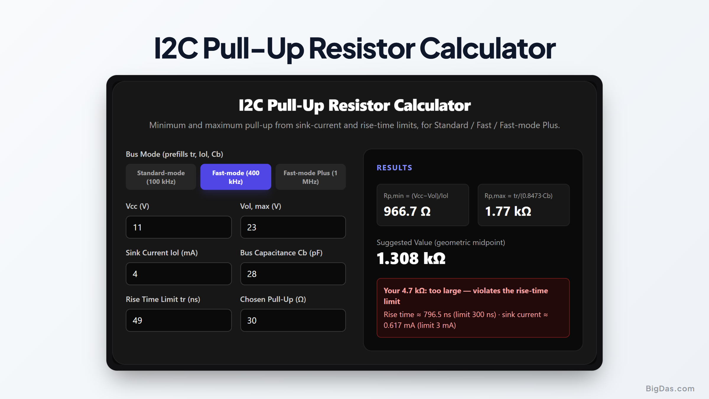
I2C Pull-Up Resistor Calculator
 Generated infographic and interface snapshot for I2C Pull-Up Resistor Calculator
Find the safe pull-up range for any I2C bus before your waveforms turn into sawtooth soup.
Free I2C Pull-Up Resistor Calculator Online. Big Das
I2C looks simple: two wires, open-drain drivers, one resistor per line. The wrong pull-up value silently corrupts the whole bus. Too small and the devices cannot sink enough current to pull the line low. Too large and the rising edge never reaches the logic-high threshold before the next clock edge. This calculator applies both limits from the I2C specification and returns the valid range, a suggested value, and a check of the resistor you already planned to use.
What Is an I2C Pull-Up Resistor?
Every I2C line (SDA and SCL) is open-drain. Devices can only pull the line low, never high. The pull-up resistor to Vcc is what returns the line to logic high. Rp is a two-sided compromise:
- Lower bound (sink current): when a device pulls low, current flows through Rp. If Rp is too small, the current exceeds what drivers can sink while keeping Vol within spec (3 mA for Standard/Fast mode, 20 mA for Fast-mode Plus).
- Upper bound (rise time): the bus capacitance Cb (traces, pins, wires, typically 100 to 400 pF) charges through Rp. If Rp is too large, the RC rise time exceeds the spec maximum (1000 ns at 100 kHz, 300 ns at 400 kHz, 120 ns at 1 MHz).
How to Use the Tool
- Pick the bus mode: Standard, Fast, or Fast-mode Plus. The tool prefills the spec's rise-time and sink-current limits and a typical bus capacitance.
- Enter Vcc and Vol(max) from the device datasheet.
- Adjust bus capacitance and rise time if the bus differs from the defaults.
- Read Rp,min and Rp,max plus a suggested geometric-midpoint value.
- Enter the chosen resistor to verify its rise time and sink current against the limits.
Any standard resistor between Rp,min and Rp,max is valid. Closer to the maximum means lower power. Closer to the minimum means sharper edges.
The Formulas
- Minimum pull-up (sink current): $R_{p,min} = \frac{V_{cc} - V_{ol}}{I_{ol}}$
- Maximum pull-up (rise time): $R_{p,max} = \frac{t_r}{0.8473 \times C_b}$
- Resulting rise time for a chosen Rp: $t_r \approx 0.8473 \times R_p \times C_b$
The constant 0.8473 is $\ln(7/3)$, the exact RC time taken to rise from the 30% to the 70% logic thresholds defined by the I2C specification.
Worked Example
A Fast-mode (400 kHz) bus at 3.3 V: Vol = 0.4 V, Iol = 3 mA, Cb = 200 pF, tr(max) = 300 ns.
$R_{p,min} = \frac{3.3 - 0.4}{0.003} = 967\ \Omega$
$R_{p,max} = \frac{300\ \text{ns}}{0.8473 \times 200\ \text{pF}} = 1.77\ \text{k}\Omega$
Suggested value $\approx \sqrt{967 \times 1770} \approx 1.3\ \text{k}\Omega$
A common 4.7 kΩ pull-up would push the rise time to ~800 ns, well past the 300 ns limit. That is the kind of mistake this tool catches instantly.
Common Use Cases
Long sensor buses accumulate capacitance fast. Check whether 4.7 kΩ resistors still meet the rise-time budget. Mixed-voltage level shifting needs each side computed with its own Vcc. Battery-powered designs push Rp toward the maximum to save sink current. Fast-mode Plus bring-up often reveals boards where no legal pull-up exists and a bus buffer is required.
Frequently Asked Questions
Why 0.8473 and not simply RC?
Rise time is defined between the 30% and 70% thresholds of Vcc, not between 0% and 100%. For an RC charge curve, the time between those two points is $\ln(0.7/0.3) = \ln(7/3) \approx 0.8473$ time constants. Plain RC would be exact only at one time constant (63%), underestimating the true edge time.
What happens if Rp,min is above Rp,max?
No single resistor satisfies both limits. The tool flags the conflict instead of returning an impossible answer. Reduce the bus capacitance (shorter traces, fewer devices), slow the bus to relax the rise-time budget, or use a bus buffer to isolate segments.
Should I pick the suggested midpoint value?
The geometric midpoint $\sqrt{R_{p,min} \times R_{p,max}}$ balances edge sharpness against power consumption and works as a default. Prefer values near Rp,max for battery life, or near Rp,min for maximum speed margin, then verify the chosen resistor in the tool.
Do both SDA and SCL need the same value?
They should both respect the same limits, but they can differ if one line carries more capacitance than the other. This is common in level-shifted buses or when SCL drives many devices. Compute each line with its own capacitance.