LC Resonant Frequency Calculator
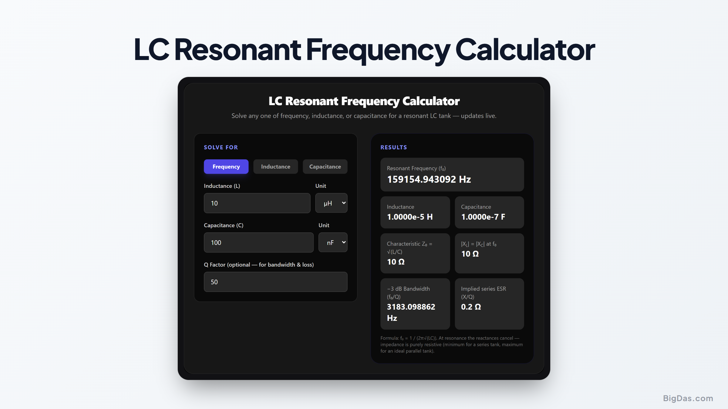
 Interface snapshot for the LC Resonant Frequency Calculator
Solve resonance, inductance, or capacitance for any LC tank directly in your browser.
Free LC Resonant Frequency Calculator Online. Big Das
Resonant LC circuits sit at the core of radios, filters, oscillators, and matching networks. When you're designing a shortwave front end, scoping a crystal radio, or debugging an EMI filter, one question keeps coming up: where does this tank resonate?
The Big Das LC Resonant Frequency Calculator handles the resonance equation in any direction, find frequency from L and C, or solve for the inductance or capacitance needed to hit a target frequency. Characteristic impedance and reactances are shown alongside.
What Is LC Resonance?
An inductor and a capacitor swap energy back and forth: current ramps up through the inductor, charges the capacitor, then the capacitor discharges back through the inductor. At one specific frequency the two reactances are equal in magnitude and opposite in phase, they cancel, and the circuit resonates.
- In a series LC, impedance drops to a minimum (just the parasitic resistance) at resonance.
- In a parallel LC, impedance peaks, which is why parallel tanks work well as bandpass selectors.
How to Use the Calculator
- Choose what to solve for: Frequency, Inductance, or Capacitance.
- Enter the other two values with their units: nH to H for inductance, pF to F for capacitance, Hz to GHz for frequency.
- Optionally enter a Q factor if you want the −3 dB bandwidth and the equivalent series resistance implied by that Q.
- Read the results live: resonant frequency, both component values in SI units, the tank's characteristic impedance √(L/C), the reactance magnitude at resonance, and (with Q supplied) bandwidth and ESR.
The Formulas
- Resonant frequency: $$f_0 = \frac{1}{2\pi\sqrt{LC}}$$
- Solve for L: $$L = \frac{1}{(2\pi f)^2 C}$$
- Solve for C: $$C = \frac{1}{(2\pi f)^2 L}$$
- Characteristic impedance: $$Z_0 = \sqrt{\frac{L}{C}}$$
- Reactance at resonance: $$|X_L| = |X_C| = 2\pi f_0 L = Z_0$$
- Bandwidth (given Q): $$BW = \frac{f_0}{Q}$$ and implied ESR: $$R = \frac{X_L}{Q}$$
Worked Examples
- AM radio coil: L = 200 µH, C = 100 pF → $f_0 = \frac{1}{2\pi\sqrt{200 \times 10^{-6} \cdot 100 \times 10^{-12}}} \approx 1.125\text{ MHz}$, mid-band on the AM dial.
- FM band trap: targeting 98 MHz with 100 pF → $L = \frac{1}{(2\pi \cdot 98 \times 10^6)^2 \cdot 100 \times 10^{-12}} \approx 26.4\text{ nH}$, roughly five turns of wire on a 5 mm former.
- Tank impedance: 10 µH with 100 pF gives $Z_0 = \sqrt{\frac{10 \times 10^{-6}}{100 \times 10^{-12}}} \approx 316\ \Omega$, the reactance each element presents at its 5.03 MHz resonance.
Common Use Cases
- Designing bandpass and notch filters for receivers and transmitters.
- Choosing trimmer capacitor ranges to cover a desired tuning span.
- Predicting self-resonant frequency of inductors and chokes from their parasitic capacitance.
- Estimating filter selectivity from measured or specified Q.
Frequently Asked Questions
Why do my measured results differ from the calculated frequency?
Real components carry parasitics: inductors have winding capacitance, capacitors have lead inductance, and both have resistance. Above the self-resonant point an inductor behaves like a capacitor. Stray layout capacitance (often 1 to 5 pF on a breadboard) also lowers the true resonance, especially with small capacitors.
What does the Q factor actually tell me?
Q (quality factor) compares stored energy to lost energy per cycle. Higher Q means a sharper, more selective resonance and lower component losses. Air-core inductors reach Q of 100 to 400; surface-mount chip inductors are often 20 to 60.
What is the √(L/C) impedance used for?
It is the tank's characteristic impedance, the magnitude of both reactances at resonance. It defines the voltage/current scaling inside the resonator and is the starting point for matching-network and quartz-crystal-equivalent-circuit analysis.
Does this calculator work for parallel resonance too?
Yes, the resonant frequency of an ideal parallel tank uses exactly the same formula. What changes is the impedance behavior: a series tank dips to its ESR at f₀, while a parallel tank peaks near Q·Z₀.
Can I solve for a variable using decimal or non-standard units?
Yes, enter values in any of the supported prefixes (pF to farads, nH to henries, hertz to gigahertz) and the tool converts everything to SI before computing, so mixed-unit problems work without extra steps.