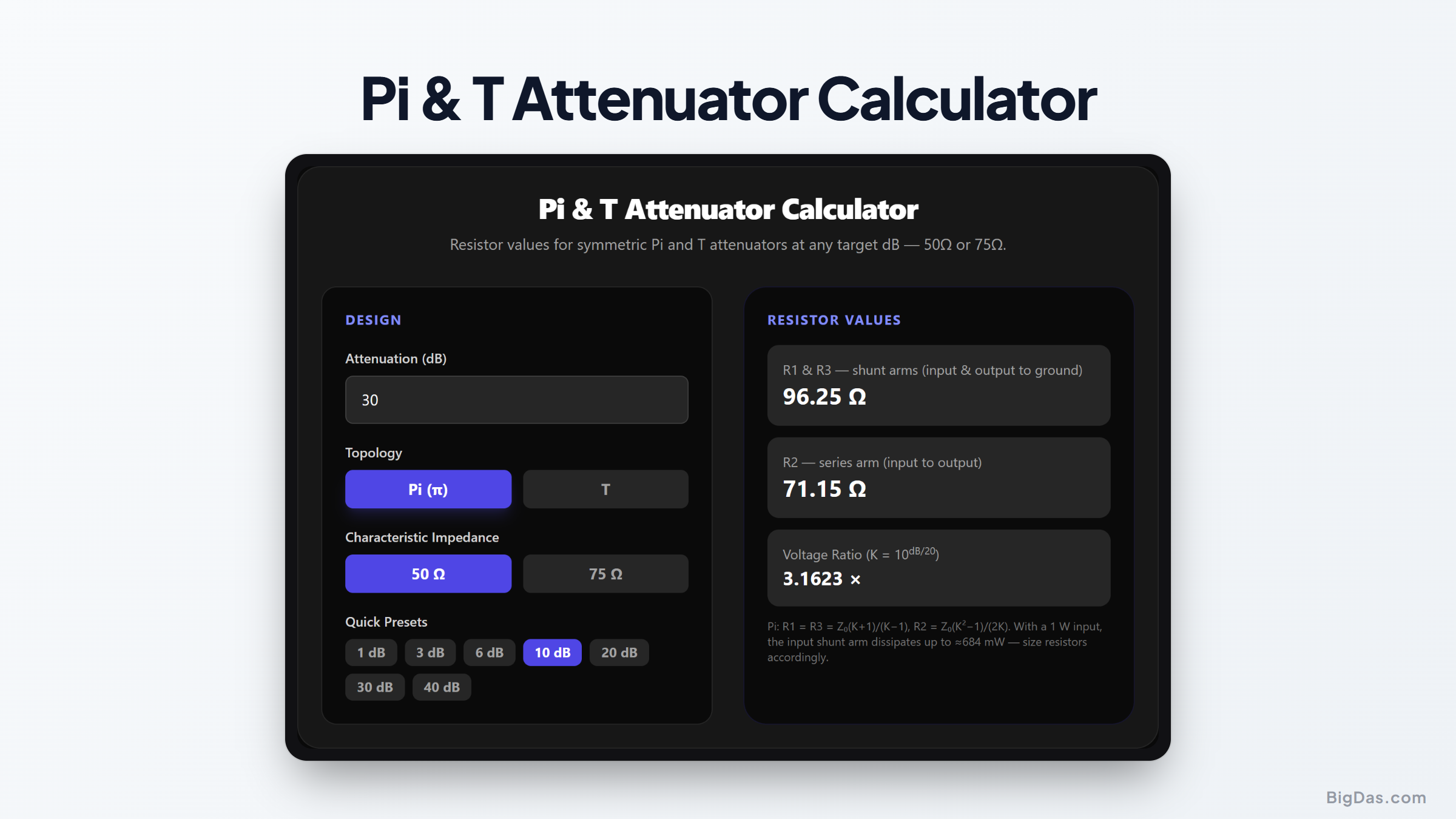
Pi & T Attenuator Calculator
 Generated infographic and interface snapshot for Pi & T Attenuator Calculator
Design matched Pi and T RF pads with the exact resistor values for 50 Ω or 75 Ω systems.
Pi & T Attenuator Calculator
A fixed RF attenuator needs to stay impedance-matched. This calculator computes resistor values for Pi and T pads at any attenuation, for 50 Ω, 75 Ω, or a custom impedance.
What the Calculator Does
An attenuator (or pad) reduces signal power by a fixed amount while staying impedance-matched. The calculator designs two classic three-resistor topologies:
- Pi attenuator: a shunt resistor at each port with a series resistor between them.
- T attenuator: two series resistors with a shunt to ground between them.
A simple voltage divider does not maintain matching. A proper Pi or T pad presents the same impedance at source and load, so reflections stay controlled and the dB drop is predictable. This matters in 50 Ω RF and 75 Ω video systems.
How to Use It
- Enter the attenuation in dB (for example,
10). - Choose the impedance: 50 Ω, 75 Ω, or a custom Z0.
- Read the Pi values: shunt R1/R3 and series R2.
- Read the T values: series R1/R3 and shunt R2.
- Pick standard parts: use the nearest E24/E96 values.
Formulas
The voltage ratio constant K comes from the dB value:
K = 10^(dB / 20)
For a T attenuator:
R1 = R3 = Z0 × (K - 1) / (K + 1)
R2 = 2 × Z0 × K / (K^2 - 1)
For a Pi attenuator:
R1 = R3 = Z0 × (K + 1) / (K - 1)
R2 = Z0 × (K^2 - 1) / (2 × K)
All resistances are in ohms, for a pad that matches Z0 at both ports.
Worked Example
Design a 10 dB, 50 Ω pad:
K = 10^(10/20) ≈ 3.162
T topology:
R1 = R3 = 50 × (3.162 - 1) / (3.162 + 1) ≈ 25.97 ΩR2 = 2 × 50 × 3.162 / (3.162^2 - 1) ≈ 35.14 Ω
Two ~26 Ω series resistors and one ~35 Ω shunt form a matched 10 dB T-pad.
Pi topology at the same 10 dB:
R1 = R3 = 50 × (3.162 + 1) / (3.162 - 1) ≈ 96.25 ΩR2 = 50 × (3.162^2 - 1) / (2 × 3.162) ≈ 71.15 Ω
Both networks present 50 Ω at either port and deliver 10 dB of loss.
Common Use Cases
- RF test benches: protect power meters or spectrum analyzers from high signal levels.
- Antenna matching: reduce a hot signal while keeping a 50 Ω feedline matched.
- Amateur radio: build inline pads between a transceiver and an amplifier.
Frequently Asked Questions
What is the difference between a Pi and a T attenuator?
Both are three-resistor matched pads. A Pi uses two shunt resistors around a series resistor; a T uses two series resistors around a shunt to ground. Same dB loss and match, different resistor values.
How do I calculate the resistor values for a 10 dB, 50 Ω attenuator?
Convert dB to a voltage ratio: K = 10^(dB/20) ≈ 3.162. T-pad: R1 = R3 ≈ 25.97 Ω, R2 ≈ 35.14 Ω. Pi-pad: R1 = R3 ≈ 96.25 Ω, R2 ≈ 71.15 Ω.
Does a Pi or T attenuator work in both directions?
Yes. Both are symmetrical networks with the same loss either way.
Can I use this calculator for 75 Ω systems?
Yes. Set Z0 to 75 Ω (or any value) and the resistors scale for video, cable TV, or other 75 Ω work.
What happens if I use standard resistor values instead of the exact ones?
Small deviations barely move the attenuation or return loss. The nearest E24/E96 value usually shifts the loss by a fraction of a dB, which is fine for most applications.
Why does the math use K = 10^(dB/20) instead of dB/10?
The pad equations are written from the voltage ratio, and dB for voltage uses 20 × log10. K is simply that voltage constant.