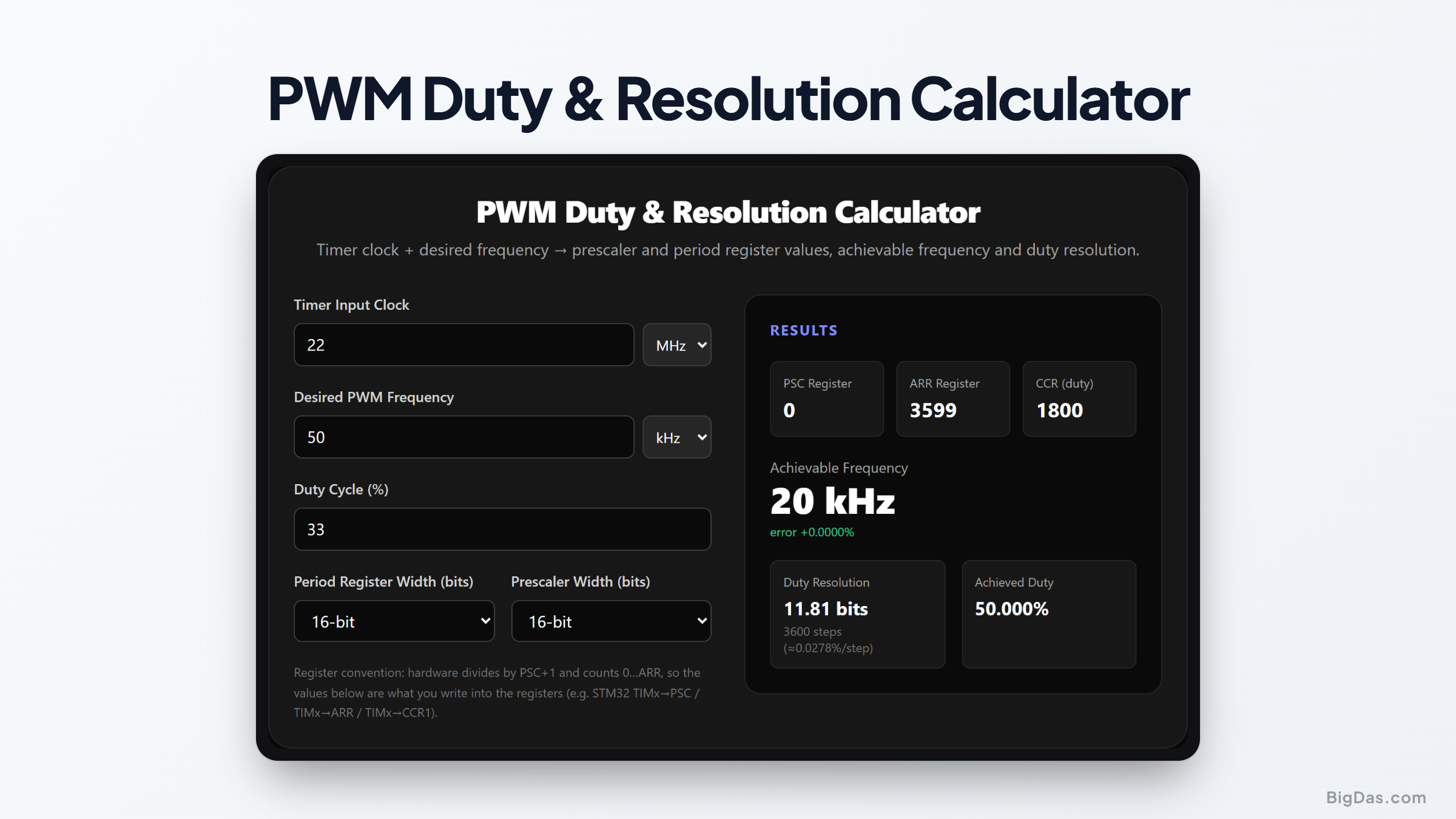
PWM Duty & Resolution Calculator
 Generated infographic and interface snapshot for PWM Duty & Resolution Calculator
Timer clock in, PSC/ARR register values out, with the true frequency and duty resolution.
Free PWM Duty & Resolution Calculator Online. Big Das
Configuring a hardware PWM peripheral means answering one deceptively simple question: *what do I write into the prescaler (PSC) and auto-reload (ARR) registers?
- Pick poorly and your LED flickers, your motor whines at 400 Hz, or your duty resolution collapses to a handful of steps. Our free PWM Duty & Resolution Calculator converts your timer input clock and target frequency into exact register values, then reports the real achievable frequency and resolution.
The PWM Frequency Equation
A timer-based PWM channel divides its input clock by the prescaler, counts up to the period register, and toggles the output when the counter passes the compare value:
$$f_{PWM} = \frac{f_{CLK}}{(PSC + 1) \times (ARR + 1)}$$
Every microcontroller divides by PSC+1 and counts 0 through ARR, so the register values are always one less than the division factors. The duty cycle is set by the compare register: duty = CCR / (ARR + 1).
The calculator first finds the smallest prescaler that lets the period fit into your register width, then rounds the period to the nearest integer, minimising frequency error automatically.
How to Use the Tool
- Enter the timer input clock (with Hz/kHz/MHz units), check your clock tree; on an STM32 the timer clock is often doubled relative to the APB clock when the APB prescaler is not 1.
- Enter the desired PWM frequency.
- Enter the duty cycle in percent to get the compare (CCR) value.
- Select the period and prescaler register widths for your target (8/16/32-bit).
- Read PSC, ARR, CCR, the achievable frequency, its error, and the duty resolution in bits, updated live.
Duty Resolution: The Hidden Variable
Resolution in bits is log2(ARR + 1), the number of discrete duty steps between 0% and 100%. Some common examples:
- 72 MHz clock → 20 kHz PWM: ARR = 3599, resolution = 11.8 bits (3600 steps, 0.028%/step)
- 16 MHz clock → 50 Hz servo PWM (PSC = 15, ARR = 19999): resolution = 14.3 bits
- 16 MHz clock → 1 MHz PWM: ARR = 15, resolution = 4 bits, only 16 duty levels
High frequency and fine granularity fight each other. If the tool shows a coarse resolution, accept a lower frequency or raise the timer clock.
Worked Example: BLDC ESC at 20 kHz from a 72 MHz STM32 Timer
- Total division needed: 72,000,000 / 20,000 = 3600
- Smallest prescaler that fits 3600 into 16-bit ARR: PSC = 0 (divides by 1)
- ARR = 3599 → actual frequency 72 MHz / 3600 = 20 kHz exactly
- At 50% duty, CCR = 1800; resolution 11.8 bits
Common Use Cases
- DC motor / H-bridge drives: keep PWM above 20 kHz to silence audible whine.
- Servo and ESC control: the 50 Hz, 1 to 2 ms pulse protocol resolves trivially from any timer.
- LED dimming: 1 to 10 kHz avoids visible flicker and camera banding.
- DAC replacement: a PWM + RC low-pass makes a slow analog output; resolution bits directly map to effective DAC bits.
Frequently Asked Questions
Why are PSC and ARR one less than the division factors?
Timers divide by (PSC+1) and count 0 through ARR inclusive. Zero is a legal register value meaning "divide by one", so maximum division from a 16-bit prescaler is 65536, not 65535. The calculator applies this convention, so the values shown can go straight into the registers.
The tool warns my frequency is too low, what now?
You have hit the maximum division (prescaler × full period register). Options: slow the timer clock in the RCC/clock tree, use a cascaded timer, or switch to a 32-bit timer (TIM2/TIM5 on STM32).
Why does duty resolution matter more than frequency error?
A 0.1% frequency error is inaudible in a motor; but 4-bit duty resolution means only 16 distinct power levels. For smooth control loops and flicker-free dimming, duty granularity is usually the binding constraint.
Can I get more resolution than the counter width?
Not in hardware, but dithering the CCR value between adjacent levels at high frequency (temporal dithering) creates intermediate average duties, effectively adding bits at the cost of slight ripple.
Is 0% or 100% duty always possible?
CCR = 0 gives a solid low output and CCR = ARR+1 (where representable) gives a solid high on most hardware. Some timers cannot produce true 100%; check the datasheet for the "forced" output mode if you need guaranteed full-on.