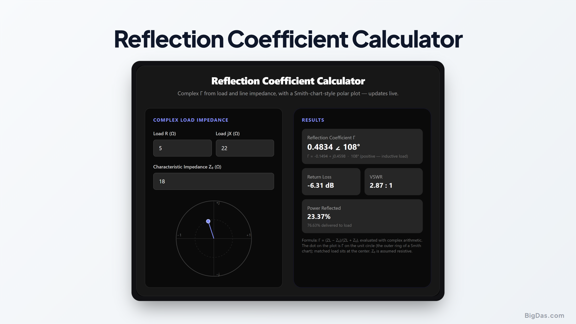
Reflection Coefficient Calculator
 Generated infographic and interface snapshot for Reflection Coefficient Calculator
See Γ, its angle, and its place on the Smith chart, instantly.
Reflection Coefficient Calculator. Big Das
Every RF design meeting starts with the same question: how much of my wave bounces back? The Big Das Reflection Coefficient Calculator computes the complex reflection coefficient from load impedance R + jX and reference impedance Z₀, shows both magnitude and phase, plots Γ on a polar, Smith-chart-style circle, and derives return loss and VSWR. Everything runs client-side and updates live.
What Is the Reflection Coefficient?
The reflection coefficient, written Γ (Gamma), is a complex number that tells you, at a single point on a transmission line, what fraction of an incident voltage wave turns around and heads back toward the source. Its magnitude runs from 0 (a perfect match) to 1 (full reflection). Its phase tells you what kind of mismatch you have, inductive loads push Γ to the upper half of the chart, capacitive loads to the lower half.
That combination of magnitude and phase is what a network analyzer displays, and what sits at the heart of the Smith chart. The polar plot in this calculator is the outer ring of that chart: the unit circle, inside which every passive load must live.
How to Use the Reflection Coefficient Calculator
- Enter the load resistance R (Ω) of your antenna, filter output, or device under test.
- Enter the load reactance jX (Ω): positive for inductive, negative for capacitive; leave as 0 for resistive loads.
- Enter Z₀ (Ω): the characteristic impedance of your system, typically 50 Ω or 75 Ω.
- Read the results panel: Γ in rectangular and polar form, phase with an inductive/capacitive hint, VSWR, return loss, reflected-power percentage, and the live polar plot.
The Formulas Used
Γ = (ZL − Z₀) / (ZL + Z₀), ZL = R + jX
|Γ| = sqrt(Re(Γ)² + Im(Γ)²)
∠Γ = atan2(Im(Γ), Re(Γ))
VSWR = (1 + |Γ|) / (1 − |Γ|)
Return loss RL = 20·log10(|Γ|) (dB)
Power reflected = |Γ|² × 100 %
The division uses full complex arithmetic. If the denominator ZL + Z₀ comes out effectively zero, the tool flags an error instead of producing a meaningless infinity.
Worked Example
Connect a ZL = 25 + j30 Ω load to a 50 Ω line (a moderately inductive, under-resistive match, like a slightly short whip antenna):
- Numerator: 25 − 50 + j30 = −25 + j30
- Denominator: 25 + 50 + j30 = 75 + j30
- Complex division: Γ = (−25 + j30)/(75 + j30) ≈ −0.149 + j0.460
- Magnitude: √(0.0223 + 0.2114) ≈ 0.4834
- Phase: atan2(0.460, −0.149) ≈ 108.0°, inductive, as expected from the positive reactance
The tool reports |Γ| ≈ 0.483, VSWR ≈ (1+0.483)/(1−0.483) = 2.87 : 1, and return loss ≈ 20·log10(0.4834) = −6.31 dB. About 23 % of the forward power reflects.
Common Use Cases
- Antenna matching verification: enter measured S₁₁ impedance from a VNA to get the full Γ picture.
- Filter and matching-network design: checks before committing to copper and trimmers.
- Telemetry and RFID tagging, where tiny impedance drifts damage read range.
- Teaching and learning: watch Γ sweep the unit circle as you tweak R and jX.
Frequently Asked Questions
What does a phase of 0° or 180° mean?
Zero phase means the reflected voltage echoes the incident one exactly: a purely resistive mismatch with ZL > Z₀. Phase ±180° (point at the far left) means full inversion, a short or a load with ZL < Z₀.
Why is the magnitude always ≤ 1 for passive loads?
Because a passive load cannot return more power than it receives. Equality happens only at |ZL| = 0 (short) or ∞ (open). Active devices can in principle show |Γ| > 1, but passive RF loads stay inside the unit circle.
Why show the plot on a unit circle?
The unit circle is the geometric home of every passive Γ, the outer frame of the Smith chart. The radial distance from the center encodes |Γ|, and the rotation encodes phase.
Can Γ be complex even with a resistive load?
Yes, whenever Z₀ does not equal the load resistance, both R and X mismatch contribute. However, if X = 0 and R ≠ Z₀, Γ is real but non-zero: positive if R > Z₀, negative if R < Z₀.
Does the sign of jX change VSWR?
No. VSWR, return loss, and |Γ| depend only on magnitude. The reactance sign rotates Γ on the chart without changing reflection strength, but it dictates which matching component (series capacitor vs inductor) fixes the problem.
What does the tool do with a purely resistive Z₀ and an open load?
R = 0 with X = 0 means a short, Γ = −1, VSWR > 99, return loss ≈ 0 dB. Conventional "open load" cases require R to climb very high; the calculator surfaces these extremes cleanly.