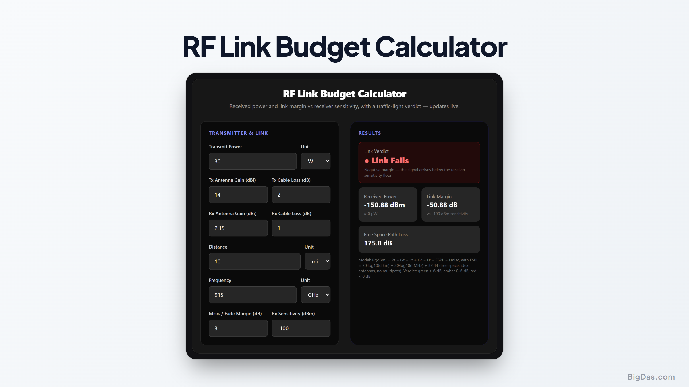
RF Link Budget Calculator
 Generated infographic and interface snapshot for RF Link Budget Calculator
Will your link close? Know before you climb the tower.
Free RF Link Budget Calculator Online. Big Das
Every wireless link is an accounting exercise: decibels gained at antennas are spent as path loss, cable loss, and fade margin before the receiver sees the signal. The Big Das RF Link Budget Calculator adds transmit power, both antenna gains, cable and connector losses, free-space path loss, and a misc. losses allowance, then compares the result against the receiver's sensitivity. A traffic-light verdict updates live.
What Is a Link Budget?
A link budget is the arithmetic of a radio path, in decibels. It starts with transmit power, adds the focusing of the Tx and Rx antennas, subtracts cable losses on both ends and the free-space path loss across the gap, finishes with an allowance for fading, and answers one question: is the received power still above the receiver's sensitivity floor? The excess is the link margin.
Link budgets are how RF engineers decide whether a LoRa node reaches the gateway, whether a Wi-Fi point-to-point bridge has enough headroom for rain, or whether an FPV drone video feed survives a range extension. The tool follows the standard convention: gains are positive, losses are positive numbers that get subtracted.
How to Use the RF Link Budget Calculator
- Transmit power: in dBm, watts, or mW, with the antenna-side cable or connector loss (dB) it must survive.
- Tx and Rx antenna gains (dBi) and their cable losses (dB).
- Geography: link distance (m / km / mi) and frequency (Hz / kHz / MHz / GHz).
- Misc. / fade margin (dB): an allowance for rain, multipath, or alignment error; 3 dB is a common planning figure.
- Receiver sensitivity (dBm): from the radio's datasheet (typically −90 to −130 dBm).
- Read the verdict: the panel shows received power, FSPL, and link margin, colour-coded green / amber / red.
The Formulas Used
FSPL(dB) = 20·log10(d_km) + 20·log10(f_MHz) + 32.44
Pr(dBm) = Pt + Gt − Lt + Gr − Lr − FSPL − Lmisc
Margin = Pr − Sensitivity
Verdict = green if Margin ≥ 6 dB,
 amber if 0 ≤ Margin < 6 dB,
 red if Margin < 0 dB
The 6 dB green threshold corresponds to a factor-of-2 voltage uncertainty or roughly a doubling of distance, the minimum sensible fade reserve for non-critical links.
Worked Example
Point-to-point Wi-Fi bridge:
- $P_t$ = 30 dBm (1 W), $G_t$ = 14 dBi, $L_t$ = 2 dB
- $G_r$ = 2.15 dBi, $L_r$ = 1 dB
- Distance 10 km at 915 MHz ISM
- Misc. losses = 3 dB, sensitivity = −100 dBm
$$FSPL = 20·\log_{10}(10) + 20·\log_{10}(915) + 32.44 = 20 + 59.23 + 32.44 = 111.67 \text{ dB}$$
$$P_r = 30 + 14 − 2 + 2.15 − 1 − 111.67 − 3 = −71.52 \text{ dBm}$$
$$Margin = −71.52 − (−100) = +28.48 \text{ dB} \rightarrow \text{green}$$
The link survives quadruple the distance or a deep fade.
Common Use Cases
- Wi-Fi / WISP point-to-point bridges and back-haul planning.
- LoRa, Sigfox, and other LPWAN links to gateways.
- FPV and drone video links at 900 MHz, 2.4 GHz, or 5.8 GHz.
- Amateur microwave and EME (moonbounce) initial feasibility checks.
- Cellular IoT deployments where sensitivity figures come straight from a module datasheet.
Frequently Asked Questions
What is free-space loss "misc." vs fade margin?
$L_{misc}$ covers everything not already itemized: connector losses beyond cable loss, polarization mismatch, modest rain fade, antenna mispointing. A 3 dB entry is a common planning reserve; harsher terrain or tropical rain can need 10 dB or more.
Why green at 6 dB specifically?
Six dB means the link can absorb a factor-of-2 drop in voltage, a 4× power dip, or a doubling of distance. Below that the margin exists but is thin; at exactly 0 dB the link is balanced on a knife edge in perfect conditions. Negative margin means it will not close.
Can antenna gain be negative or a loss be negative?
Gains may be negative (compact antennas often are). Losses must be non-negative, a negative loss would be an unaccounted-for gain and breaks the budget's bookkeeping. The tool flags such inputs.
Does FSPL include real-world obstacles?
No. FSPL is the minimum loss with a clear Fresnel path. Trees, buildings, and knife-edge diffraction eat additional dB that should either be entered as misc. losses or added via a path-specific propagation model.
What if receiver sensitivity is given in µV?
Convert it first: $dBm = 20·\log_{10}(V_{rms}) − 113.01$ for a 50 Ω input (1 µV ≈ −107 dBm). Plug the dBm value straight in as sensitivity.
Is EIRP taken into account?
Yes, implicitly. EIRP = $P_t + G_t$. The calculator's received-power math treats antenna gains symmetrically on both ends, which is the standard Friis formulation.