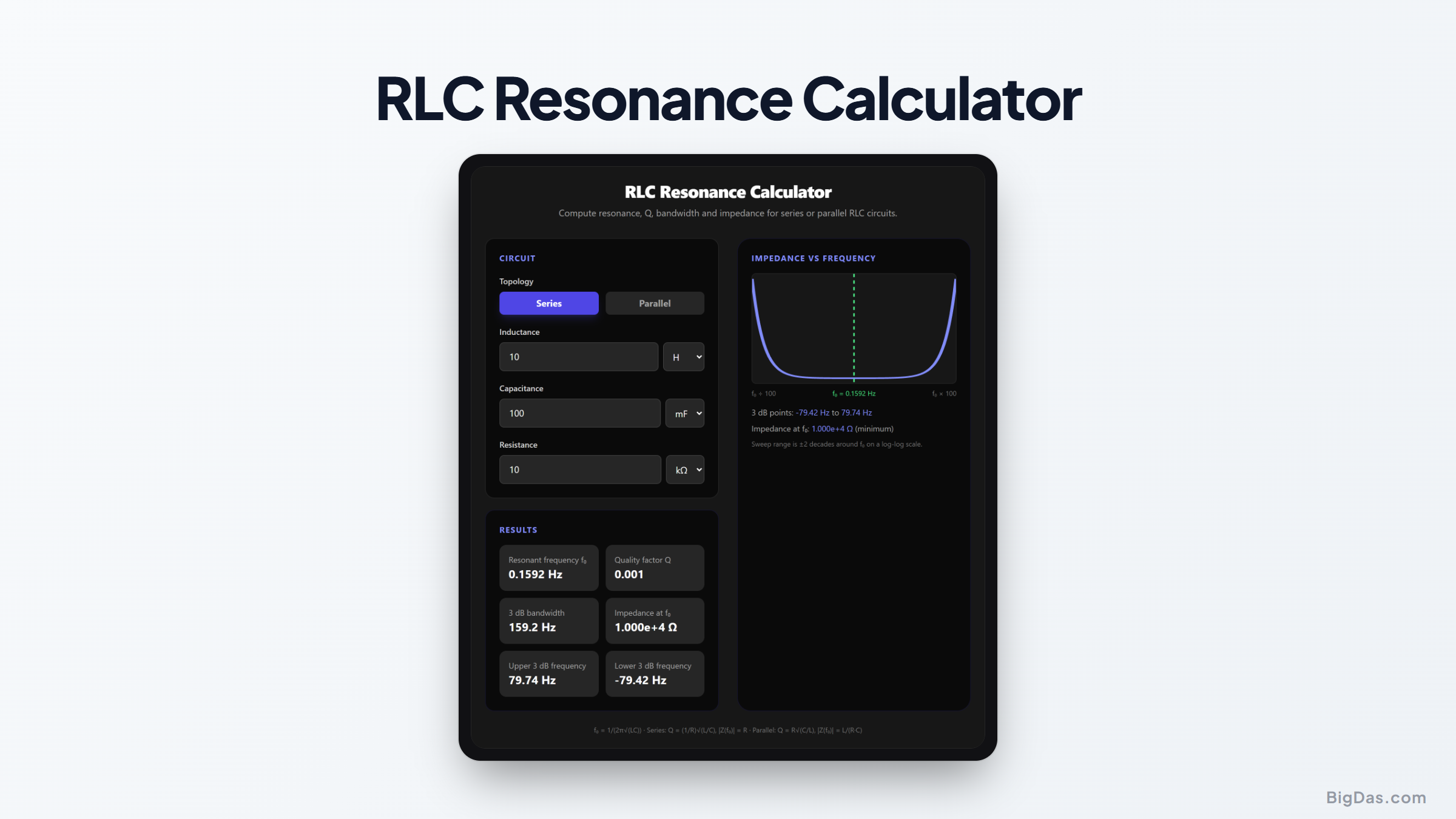
RLC Resonance Calculator
 Generated infographic and interface snapshot for RLC Resonance Calculator
Find resonance, Q and bandwidth for any series or parallel tank circuit.
Free RLC Resonance Calculator Online. Big Das
The Big Das RLC Resonance Calculator computes resonant frequency, quality factor, 3 dB bandwidth and impedance at resonance for series and parallel RLC circuits, with a live impedance-vs-frequency plot.
What Is RLC Resonance?
A resistor, inductor and capacitor form a resonant circuit. At the resonant frequency f₀ the inductive and capacitive reactances cancel, so a series RLC reaches minimum impedance (just R) while a parallel RLC reaches maximum impedance. Q measures how sharp that resonance is: higher Q means a narrower passband or stopband.
How to Use the RLC Resonance Calculator
- Choose Series or Parallel topology.
- Enter the inductance with its unit (µH, mH or H).
- Enter the capacitance (nF, µF or mF).
- Enter the resistance (Ω or kΩ).
- Read f₀, Q, bandwidth, impedance at f₀ and both 3 dB frequencies instantly; the plot sweeps two decades above and below f₀.
Formulas Used
Resonant frequency (both topologies):
f0 = 1 / (2π · √(L · C))

Series RLC:
Q = (1/R) · √(L/C) = ω0·L / R
|Z(f0)| = R (minimum)
|Z(f)| = √(R² + (ωL − 1/ωC)²)

Parallel RLC (loss in series with L):
Q = R · √(C/L) = R / (ω0·L)
|Z(f0)| = L / (R·C) ≈ Q²·R (maximum, for high Q)

3 dB bandwidth:
BW = f0 / Q f_low ≈ f0 − BW/2 f_high ≈ f0 + BW/2
Worked Example
Series RLC with L = 10 mH, C = 100 nF, R = 10 Ω:
- f₀ = 1 / (2π√(10×10⁻³ · 100×10⁻⁹)) ≈ 5.03 kHz
- Q = (1/10)√(10×10⁻³ / 100×10⁻⁹) ≈ 31.6
- BW = 5033 / 31.6 ≈ 159 Hz
- |Z(f₀)| = 10 Ω (the resistor alone)
Put the same parts in parallel: Q = 10·√(100nF/10mH) ≈ 0.0316, the bandwidth balloons to ≈ 159 kHz, and |Z(f₀)| = L/(R·C) = 10 kΩ maximum.
Common Use Cases
- Designing band-pass and band-stop filters
- Tuning RF tank circuits and antenna matchers
- Checking selectivity of oscillator networks
- Estimating ringing and damping in switching converters
- Coursework and lab verification for AC circuits classes
Frequently Asked Questions
Why does series resonance give minimum impedance but parallel give maximum?
At f₀ the reactances ωL and 1/ωC cancel. In series that leaves only R between the terminals; in parallel the circulating tank current means only a tiny current is drawn from the source, which appears as a very large impedance L/(R·C).
Can Q be zero or negative?
Not in a passive, physical circuit. Q requires positive R, L and C. The calculator rejects non-positive values rather than show a meaningless number.
Why is the 3 dB bandwidth f₀/Q?
At the two frequencies where reactance equals resistance the current (series) or voltage (parallel) falls to 1/√2 of its resonant value, the half-power or −3 dB points. Their separation works out to exactly f₀/Q.
Does the plot use a log scale?
Yes. Frequency and impedance are both logarithmic, sweeping two decades either side of f₀ so the resonance shape is visible regardless of component values.
What resistance should I use for a real inductor?
Use its DC resistance plus any explicit series resistor. Coil DCR dominates Q in most practical series tanks.