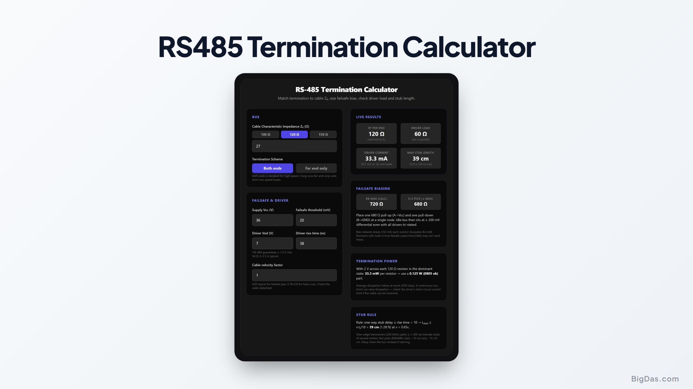
RS485 Termination Calculator
 Generated infographic and interface snapshot for RS485 Termination Calculator
Match the cable, bias the idle bus, and keep stubs short enough to matter.
Free RS-485 Termination Calculator Online. Big Das
RS-485 will happily run a kilometre, if the line is terminated, the idle bus is biased, and the stubs are short. The Big Das RS-485 Termination Calculator computes the termination resistors matched to your cable's characteristic impedance, the parallel load the driver actually faces, failsafe biasing resistors for a 200 mV idle margin, termination power dissipation at real driver voltages, and the maximum stub length from your driver's rise time.
What Is RS-485 Termination?
RS-485 is a differential, multi-drop bus over twisted pair. The cable is a transmission line with a characteristic impedance Z₀, typically 100 to 120 Ω. A signal edge hitting an unterminated end reflects, and reflections corrupt later bits. The fixes:
- Terminate both ends with Rt = Z₀. The driver then sees Rt ∥ Rt = 60 Ω on a 120 Ω bus.
- Failsafe bias at one node: a pull-up on A and pull-down on B so an idle or disconnected bus still reads as a valid mark (> 200 mV differential).
- Short stubs: a tap longer than about 1/10 of the driver's rise time acts as its own transmission line and rings.
How to Use the RS-485 Termination Calculator
- Enter cable Z₀: from the datasheet; presets for 100, 120, 150 Ω.
- Pick the termination scheme: both ends (standard) or far end only (short, slow buses).
- Enter supply, failsafe threshold, driver Vod, and rise time: from the transceiver and cable datasheets.
- Set the cable velocity factor: 0.65 is typical for twisted pair.
- Read the results: Rt per end, driver load and current, max/E12 failsafe resistors with their dissipation, termination power, and max stub length in cm and feet.
The Formulas Used ```
Termination: Rt = Z₀ (each end) Driver load: R_load = Rt/2 (both ends) or Rt (one end) Driver current: I = Vod / R_load Failsafe bias: V_bus = Vcc × R_load / (2Rb + R_load) ≥ V_fs → Rb ≤ R_load × (Vcc − V_fs) / (2 × V_fs) Termination power: P = Vod² / Rt (per resistor, dominant) Stub rule: L ≤ v × t_r / 10, v = velocity_factor × c
`V_fs = 200 mV` is the TIA/EIA-485 receiver threshold range (±200 mV); driving the idle bus beyond it guarantees a defined state.

---

## Worked Example
A 120 Ω bus, both ends terminated, 5 V supply, 200 mV failsafe, driver Vod = 2 V, rise time 20 ns, velocity factor 0.65:

- Rt = **120 Ω** per end; driver sees **60 Ω**

- Driver current = 2 V / 60 Ω = **33.3 mA**, comfortably inside any TIA-485 driver's 54 Ω / 1.5 V guarantee

- Rb max = 60 × (5 − 0.2) / (2 × 0.2) = **720 Ω** → pick **680 Ω** (E12) pull-up / pull-down

- Termination dissipation = 2² / 120 = **33 mW** per resistor, an 0805 chip part is fine

- Max stub = 0.65 × 3×10⁸ × 20 ns / 10 = **39 cm** (≈1.3 ft)

---

## Common Use Cases

- **Modbus RTU networks**: sensor and PLC buses up to 1 Mbit/s.
- **DMX512 lighting**: 120 Ω cable, both-end termination is mandatory.
- **Building automation (BACnet MS/TP)**: long runs with many drops; stub discipline matters.
- **Industrial motor drives**: noisy environments where failsafe bias prevents phantom frames.

---

## Frequently Asked Questions

### Why 60 Ω and not 120 Ω for the driver load?

Two 120 Ω terminations, one at each physical end of the cable, appear in parallel to the driver: 120 ∥ 120 = 60 Ω. TIA/EIA-485 drivers are specified to deliver at least 1.5 V into a 54 Ω load, which covers this plus 32 unit loads of receivers.

### Do I need termination on a short, slow bus?

Below roughly 100 kbit/s and a few metres, edge reflections die before the next bit and termination can be omitted, saving the constant DC load. The stub-length result tells you when the transmission-line view starts to matter: compare it against your bus length.

### Can I put failsafe resistors at every node?

No, parallel bias networks divide the effective resistance and overload the driver. One biasing node (usually the master) for the whole bus.

### My transceiver claims "true failsafe", skip the resistors?

Check what it covers: true failsafe receivers output a defined state for open, short, and idle bus, and if every receiver on the bus has it, external bias is unnecessary. Mixed-vintage buses still need the resistors.

### Why does rise time limit stub length, not bitrate?

Reflections are excited by edges, and edge speed, not bit rate, sets the frequency content. A slow-edge 250 kbit/s transceiver tolerates metre-long stubs that would break a fast MAX485 running at the same bitrate.