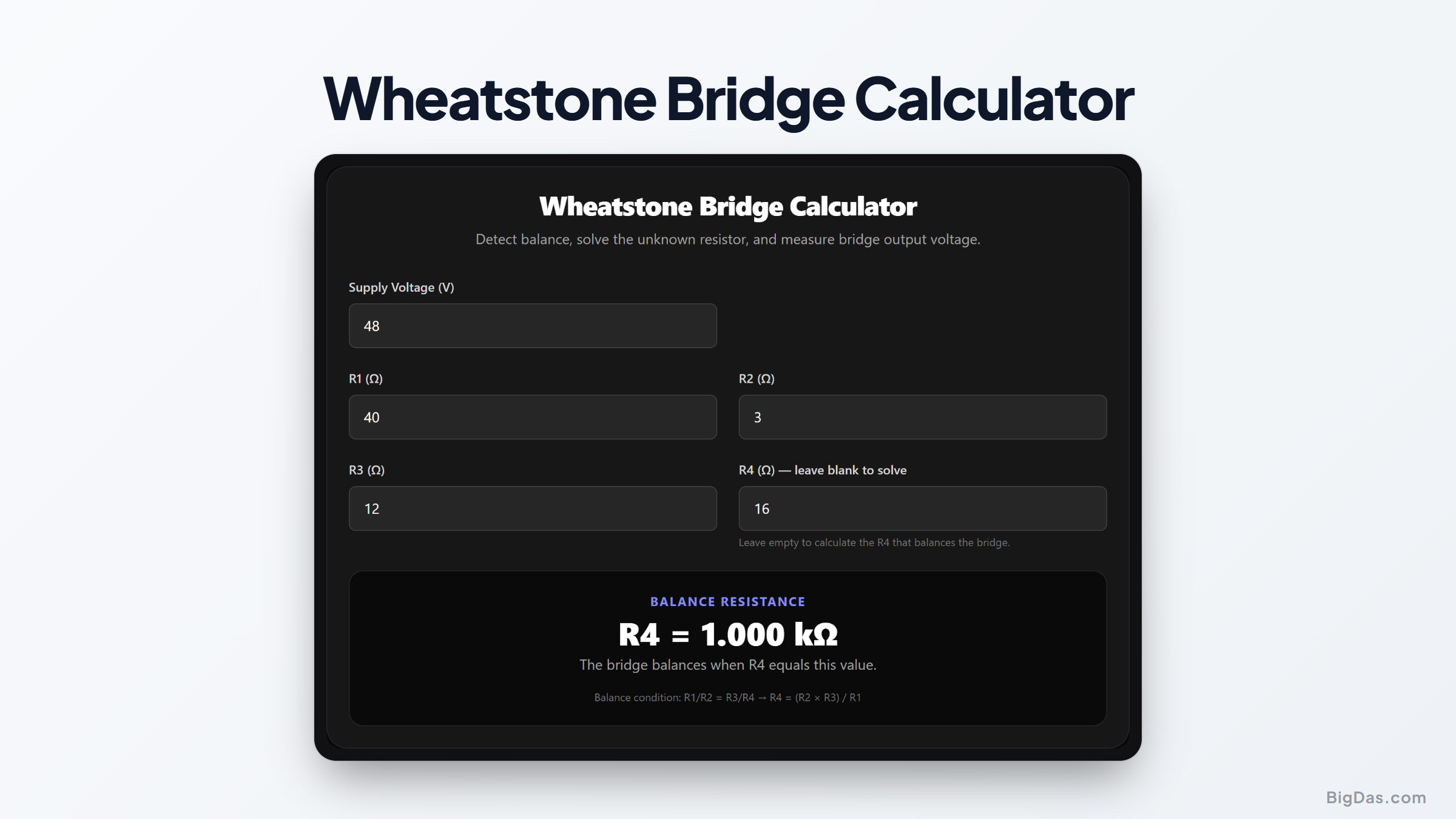
Wheatstone Bridge Calculator
 Generated infographic and interface snapshot for Wheatstone Bridge Calculator
Balance bridges, solve unknown resistors, and measure sensor output.
Free Wheatstone Bridge Calculator Online. Big Das
The Wheatstone bridge measures unknown resistances and reads small changes in sensors like strain gauges and thermistors. The Big Das Wheatstone Bridge Calculator checks whether your bridge is balanced, solves for the unknown resistor, and computes the output voltage under any imbalance.
Enter your four resistor values and supply voltage, and the tool updates live. It works for lab work, sensor design, and electronics coursework.
What Is a Wheatstone Bridge?
A Wheatstone bridge is a network of four resistors arranged in a diamond. Two resistors form one voltage divider on the left, and two more form a second divider on the right. A meter or amplifier connects between the two divider midpoints.
When the ratios on both sides are equal, the midpoints sit at the same voltage and the bridge is balanced, the output reads zero. Any mismatch produces a small differential voltage proportional to the imbalance.
Why Use a Bridge?
Bridges detect tiny changes well. A strain gauge might change resistance by only 0.1% under load, but a bridge converts that minute shift into a measurable voltage. The same principle applies to temperature sensors, pressure sensors, and precision resistance measurement.
How to Use the Wheatstone Bridge Calculator
- Enter Supply Voltage (V): The excitation voltage across the whole bridge, typically 3.3 V, 5 V, or 10 V.
- Enter R1, R2, and R3 (Ω): The three known resistors in the bridge.
- Enter R4 (Ω): The unknown or variable resistor. Leave this field blank if you want the tool to solve for the value that balances the bridge.
- Read the results: The tool shows either the balance value for R4 or the bridge output voltage, plus the individual divider voltages.
The Formulas Used
Balance Condition
A Wheatstone bridge is balanced when:
R1 / R2 = R3 / R4
Rearranged to solve for the unknown resistor:
R4_balance = (R2 × R3) / R1
Output Voltage
The voltage at the left divider midpoint is:
V1 = Vin × R2 / (R1 + R2)
The voltage at the right divider midpoint is:
V2 = Vin × R4 / (R3 + R4)
The bridge output is the difference:
Vout = V1 − V2 = Vin × [R2/(R1+R2) − R4/(R3+R4)]
Worked Example
You have R1 = 1 kΩ, R2 = 1 kΩ, and R3 = 1 kΩ, with a 5 V supply. Leaving R4 blank, the calculator shows:
R4 = 1 kΩ for balance.
Now enter R4 = 1.1 kΩ (a sensor that drifted 10%):
- V1 = 5 × 1000 / (1000 + 1000) = 2.5 V
- V2 = 5 × 1100 / (1000 + 1100) ≈ 2.619 V
- Vout = 2.5 − 2.619 ≈ −0.119 V
The negative sign tells you which divider is higher. Swap R4 back to 1 kΩ and the output returns to zero.
Common Use Cases
- Strain gauge measurement: Detect mechanical stress in beams, load cells, and pressure sensors.
- Temperature sensing: Convert a thermistor's resistance change into a voltage.
- Precision resistance measurement: Determine an unknown resistor by adjusting a known one until the bridge balances.
- Light-level detection: Convert a photoresistor's response into a readable signal.
- Education: Demonstrate voltage dividers and differential measurement in electronics labs.
Frequently Asked Questions
What does a balanced bridge mean?
A balanced bridge produces zero output voltage. Both divider midpoints sit at exactly the same potential, so no current flows through the meter between them. This is the null-detection principle behind precision measurement.
Why is the balance equation R1/R2 = R3/R4?
Because each side of the bridge is a voltage divider. The midpoints match when the ratio of top-to-bottom resistance is identical on both sides. Rearranged, this equality gives the classic balance condition.
Can I use this for AC bridges?
The formulas shown are for DC resistive bridges. AC bridges with capacitors and inductors use impedance instead of resistance, which adds phase considerations beyond this tool's scope.
How sensitive is a Wheatstone bridge?
Sensitivity depends on supply voltage and how far the bridge is from balance. Doubling the excitation voltage doubles the output for the same imbalance. Amplifiers are often needed because sensor bridges typically produce millivolt-level signals.
What if R4 is zero or negative?
Zero would short one side of the bridge, and negative resistance isn't physically realizable with passive parts. The calculator requires a positive value for R4 and shows a clear error otherwise.
Why does the output go negative?
The sign indicates the direction of imbalance. If Vout is negative, the right divider is higher than the left. Swap two resistors or reverse your reference polarity to flip the sign.