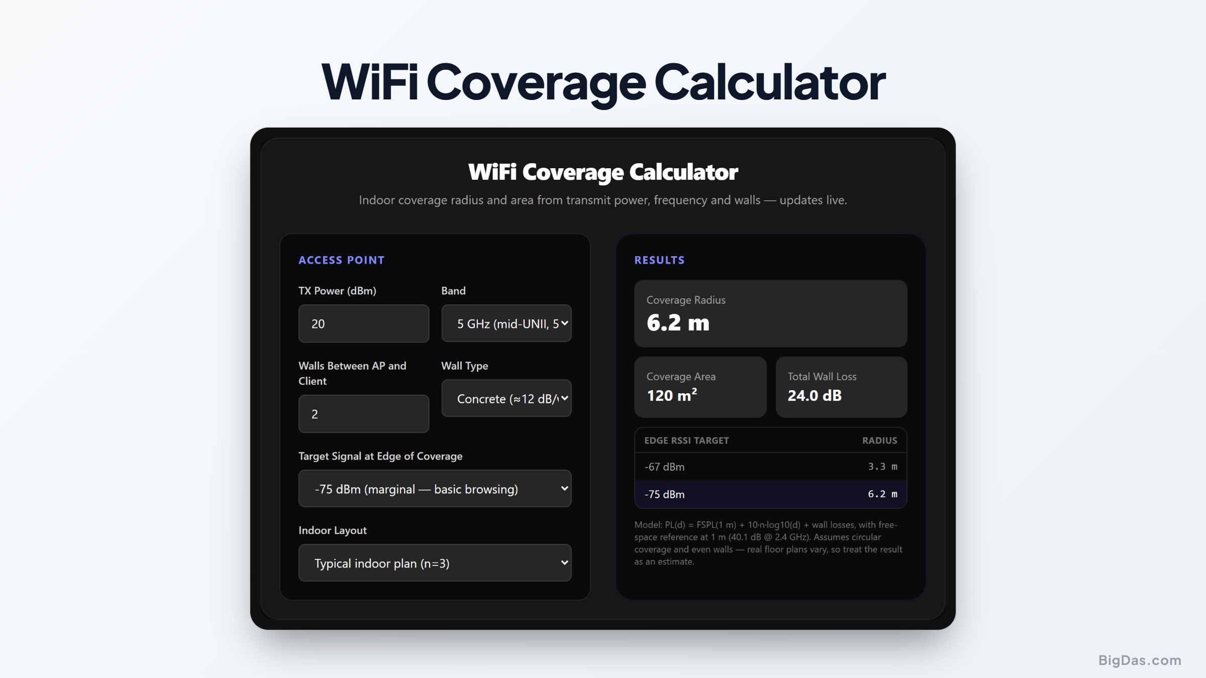
WiFi Coverage Calculator
 Generated infographic and interface snapshot for WiFi Coverage Calculator
Find out how far your access point really throws a signal indoors.
Free WiFi Coverage Calculator Online. Big Das
A 20 dBm transmit power spec on a router box means little until walls, frequency, and room layout enter the picture. The Big Das WiFi Coverage Calculator converts transmit power, band (2.4/5/6 GHz), wall count, and material into a live estimate of indoor coverage radius, floor area, and wall loss, so access point placement is based on numbers, not guesses.
No login, no survey app. The model runs entirely in your browser.
What Is Indoor WiFi Coverage?
Coverage here is the radius around an access point where clients still receive a usable signal strength (RSSI). Indoors, that radius shrinks compared with open space because:
- Higher frequencies attenuate faster: 6 GHz loses about 8 dB more than 2.4 GHz over the same distance.
- Walls absorb energy: roughly 3 to 4 dB per drywall, 6 to 10 dB per brick wall.
- Furniture, people, and partitions add scattered shadowing loss.
A common design target is -67 dBm at the cell edge for voice/video and seamless roaming; -75 dBm is marginal but workable for light browsing.
How to Use the WiFi Coverage Calculator
- Enter transmit power in dBm (typical APs: 14 to 23 dBm).
- Pick the band: 2.4 GHz, 5 GHz, or 6 GHz.
- Set the number of walls between the AP and the furthest client, and their material (drywall, brick, or concrete).
- Choose the edge-of-coverage target: -67 dBm for good, -75 dBm for marginal.
- Select the indoor layout: open plan (n=2.5), typical (n=3), or obstructed (n=4).
- Read the results: headline radius, circular coverage area, total wall loss, and a comparison of both RSSI targets appear instantly.
The Formulas Used
Free-space ref at 1 m: FSPL(1m) = 20·log10(4π·f / c)
≈ 40.1 dB @ 2.4 GHz, 47.2 dB @ 5 GHz, 47.9 dB @ 6 GHz
Indoor log-distance: PL(d) = FSPL(1m) + 10·n·log10(d) + Σ wall losses
Coverage radius: d = 10^((TX - RSSI_target - walls - FSPL(1m)) / (10·n))
Coverage area: A = π·d²
This is the ITU-R-style indoor propagation model: a free-space anchor at 1 m with a log-distance exponent n and discrete wall attenuation.
Worked Example
Typical home router: 20 dBm TX on 2.4 GHz, two drywall walls (3.5 dB each), targeting -67 dBm, typical layout n=3:
Wall loss = 2 × 3.5 = 7 dB
Budget = 20 - (-67) - 7 - 40.1 = 39.9 dB available over distance
Radius = 10^(39.9/30) ≈ 21 m
Area = π × 21² ≈ 1,410 m²
Switch to 6 GHz (FSPL(1m) = 47.9 dB there) and the same router covers only about 11.7 m before hitting -67 dBm, roughly 1.8× less radius through the walls, which is why WiFi 6E/7 mesh nodes are placed closer together.
Common Use Cases
- AP placement: Decide how many access points a floor needs before installing them.
- Band selection: Quantify the 2.4 vs 5 vs 6 GHz range trade-off for a floor plan.
- Mesh planning: Check whether a satellite node can still hear the main router through your walls.
- Site-survey prep: Produce a first-pass coverage guess to validate against a real survey.
Frequently Asked Questions
Why is my measured coverage smaller than the estimate?
The model assumes circular coverage through evenly distributed walls of one type. Real-floor mirrors, metal ducts, low-E glass, and human bodies add shadowing loss, so treat the result as an optimistic design figure and leave a few dB of fade margin.
What does the n exponent actually represent?
n is the path-loss exponent: how fast signal decays with distance. n=2 is free space; corridors can dip below 2; cluttered indoor spaces push n toward 4. This tool offers 2.5, 3, and 4 for typical office/home layouts.
Is -67 dBm the right target?
-67 dBm is the industry standard edge for voice, video, and fast-roaming applications (CCX/enterprise guidance). -75 dBm works for email and web. If you only browse, select -75 and accept a deliberately larger radius.
Does antenna gain count?
Yes, add the AP antenna gain to the transmit power figure (e.g. 20 dBm conducted + 3 dBi antenna behaves like 23 dB EIRP toward the client). Regulatory limits apply to EIRP, not conducted power.
Why does 6 GHz cover less area than 2.4 GHz?
Free-space loss rises with frequency: about 47.9 dB at 1 m for 6 GHz versus 40.1 dB for 2.4 GHz. That ~8 dB deficit is roughly 1.8× less distance at the same RSSI (at n=3), before any wall count, and walls also absorb 5/6 GHz more strongly.
Can I use this for outdoor point-to-point WiFi?
Not reliably, outdoor links follow a two-ray or free-space model (n≈2) with Fresnel-zone clearance requirements that this indoor tool doesn't model. Use the free-space reference radius it prints only as a rough bound.